Roughly three months have passed since I wrote my initial post about a machine I call “The Octo-Bouncer.” What has happend since then? In this post I talk about what parts of the machine were updated. Why they were updated and what kind of stuff the machine is able to do thanks to these updates.
So what changed?
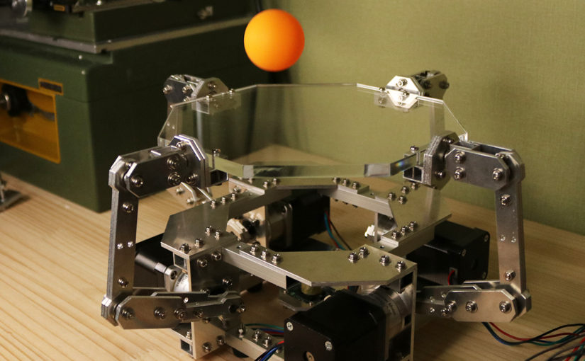
I will cut straight to the juice. Here’s what the machine is able to pull off now:
And here are all the things that changed in order to make the new bouncing patterns possible:
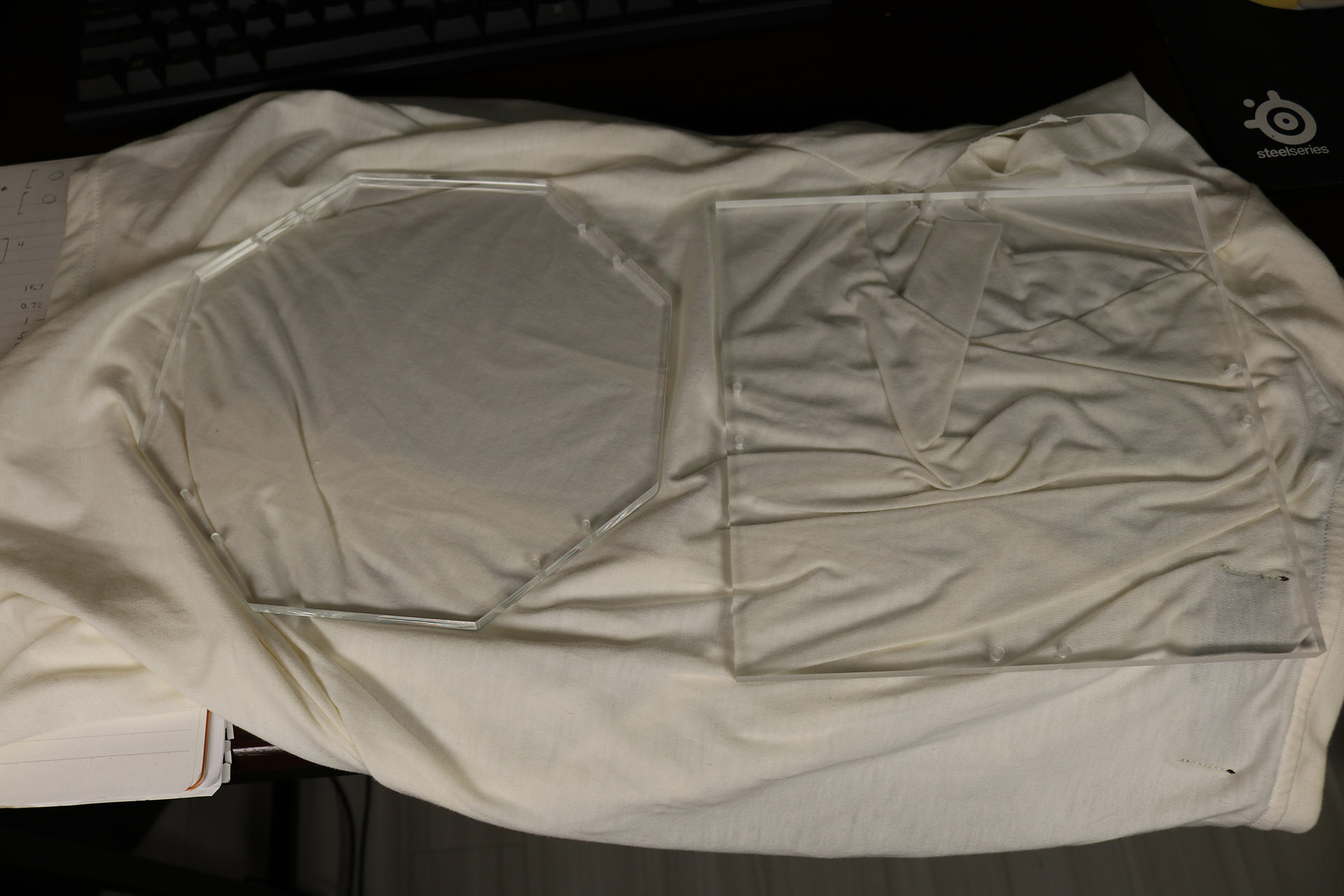
- I cut the squared acrylic plate into the shape of a octagon
- New custom ball detection algorithm
- New ball position data visualization
- Hit position prediction using gradient descent
- Plate tilt visualization
- Analytical tilt control
- Two-step bouncing
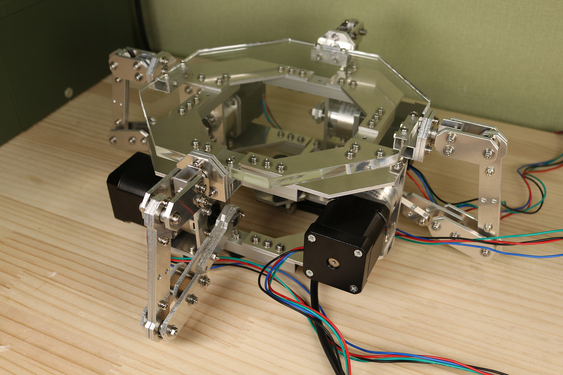
Octagonal top plate
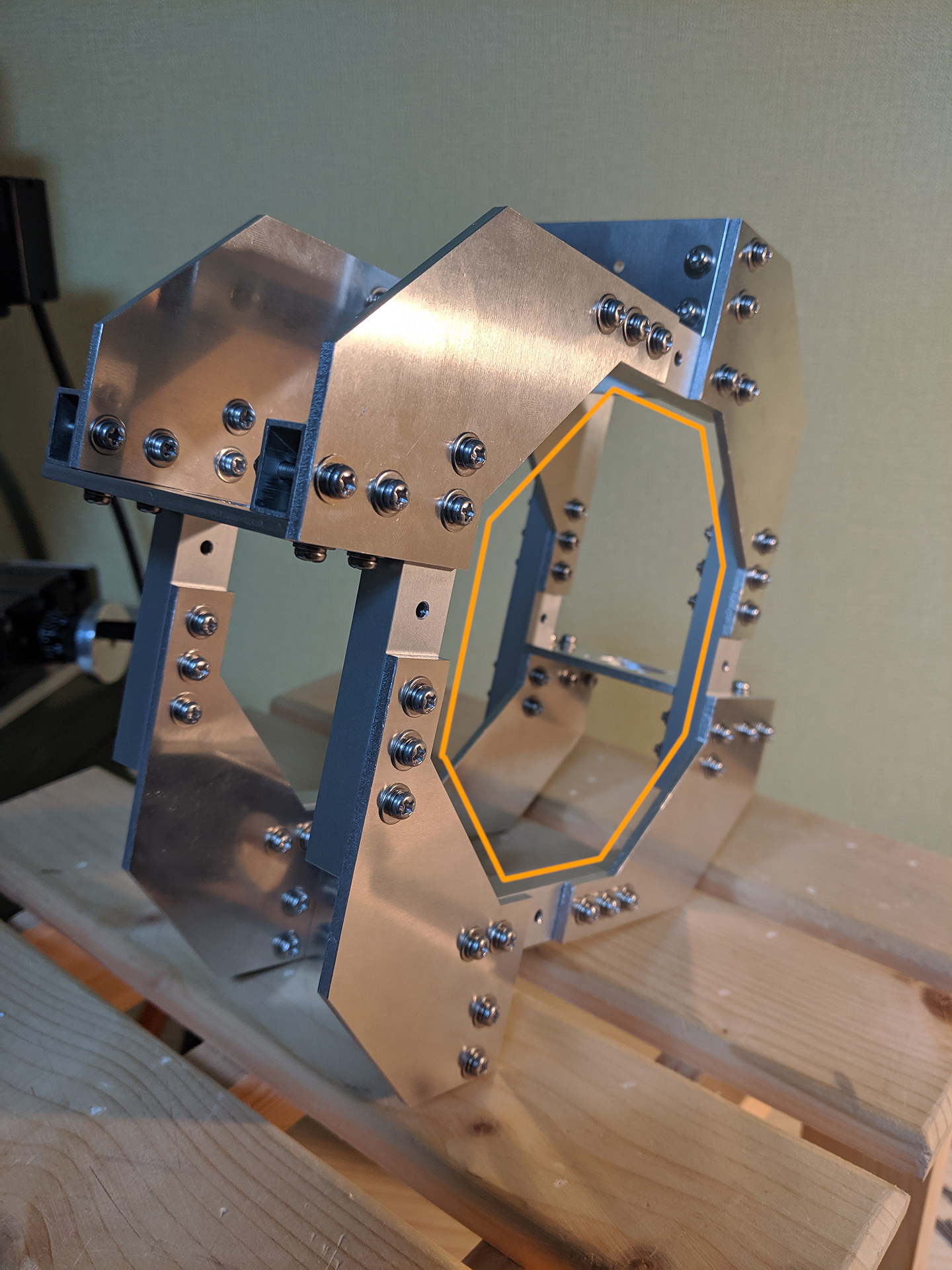
So I did what I planned on doing since I was designing this machine; I went ahead and cut the acrylic top plate into an octagon. Why didn’t I do this right away? Because I wasn’t sure whether or not I’d be able to get a good finish. Turns out cutting and polishing an acrylic plate isn’t all that hard. Here’s some pics I took while changing the top plate.
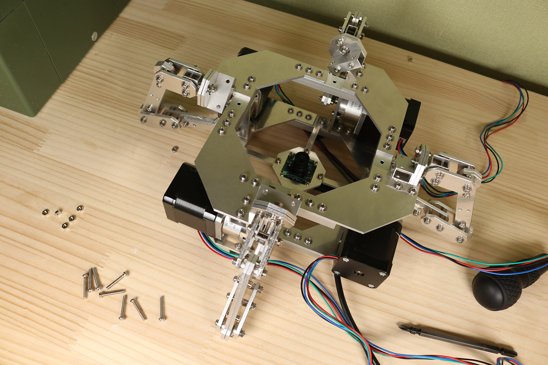
“Huh, so that’s why you call it Octo-Bouncer?” – Yes. But let me explain. It’s not only the plate. There are a lot of octagons in the design. Like here:
and here:
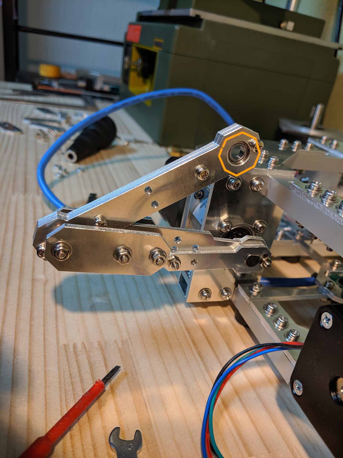
I was constantly thinking how to implement more octagons into the design while working on the aluminium build. Naming it Octo-Bouncer seemed like the only reasonable thing to do at the time.
New ball detection algorithm
“Why fix something that’s not broken? What was so bad about the old ball detection?” – there were mainly 2 things I didn’t like about using OpenCVs HT21 circle detection algorithm in this specific project:
- Too much noise in both the position and radius data
- Too slow. Wasn’t able to reliably process at 120 FPS.
Let me be very clear here. I am not bashing the HT21 circle detection algorithm. It just wasn’t the right fit for the job. HT21 shines in circumstances when there’s a lot of different shapes and edges and you want to know where the f*ck the circle is. But our image data is very clear cut from the start. Just look at it:
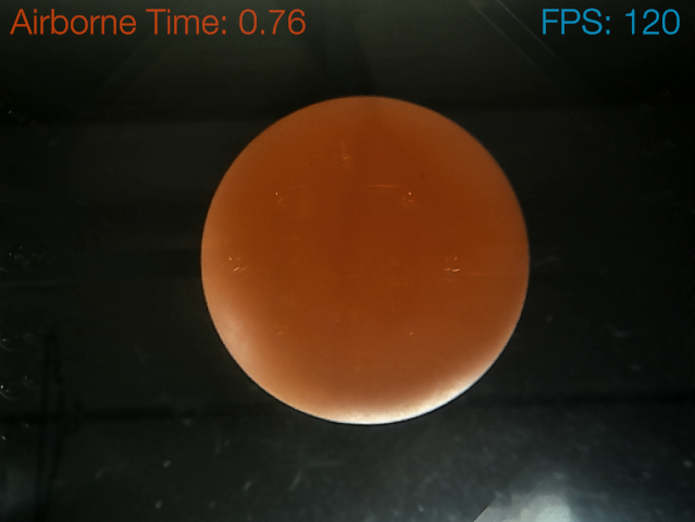
After doing a simple orange to gray scale conversion the data is even crisper.
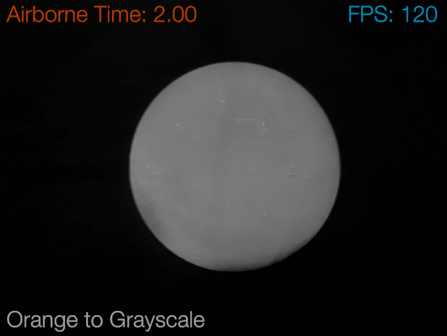
We could find the ball’s position just by counting all the bright pixels and then taking the average. Following this line of thought a bit deeper, we also see that there’s an easy way to get the ball’s radius by counting all the bright pixels and then using the fact that a circles area is equal to pi * r^2.
I did just that. It worked flawlessly. The only problem with this approach is that detecting multiple balls is only possible if we’re adding code to distinguish the different lumps of bright pixels. I went down this route for a while but the processing load quickly got out of hand and my goal of 120 FPS didn’t seem feasible.
So here’s what I ended up doing: Edge following. My current algorithm just follows around the edge of all the bright pixel lumps it is able to detect. After we got this edge data we just look at one of the edge-pixels and determine which of all the other edge pixels is the furthest away. Computing the 2D distance between these two pixels yields the diameter of the ball. And if we do this for 10 pixels randomly chosen and then only consider the 5 biggest diameters we are able to get very accurate ball data even if the ball isn’t fully visible or part of the edge isn’t appearing circely.
If you’re not convinced just look at this data:
Don’t tell me you see no difference; The custom one outperforms OpenCVs HT21 circle detection algorithm both in performance and accuracy (in this specific case that is.)
Analytical tilt control
Another big software update was the addition of analytical tilt control. Now “analytical tilt control” are just 3 words put together because I thought that they’d describes fairly well what’s going on. But do they though? What’s so analytical about this tilt control mechanism?
So here’s the idea: We’ve got a ton of accurate data describing the ball’s current state. We’ve got position, we are able to get a good approximation of the balls velocity using gradient descent on this position data. We also know how long the ball is in the air between bounces. So the idea is that with all this data and leveraging the power of basic physics we should be able to analyse the situation in such a way that there is an ideal tilt which will lead to the ball bouncing exactly to where we want it to bounce.
Analytical tilt control works well. It outperforms the PID algorithm I used up to this point. But it isn’t perfect. Every once in a while the ball will end up bouncing in an unexpected direction.
But this unexpected behavior isn’t so much caused by the tilt controlling mechanism misjudging the situation, but rather by small dirt particles on the plate (I think.) There is also a line of thought concerning the balls rotational momentum; When the ball hits the plate, some of the energy put back into the ball after the hit might be in the form of rotational momentum. This rotational momentum could influence the balls trajectory on later bounces.
But I checked the relationship between “ball suddenly bouncing in an unexpected direction” and “ball is spinning.” And the two seemed unrelated. This brings me to the current conclusion that it really must be a problem with small uneven areas in both plate and ball, since the degree to which the ball sometimes suddenly changes direction would need the plate to wrongly tilt several degrees in the wrong direction. And I also checked this possibility. On occasions where the ball acts unexpected, the plate isn’t showing an unexpected tilt. So currently I’m thinking it has to be a problem with the fact that the touching surfaces of ball and plate are actually really small and that if there’s something uneven about these small areas it will lead to the ball doing something unexpected.
I am interested in your invention and would like to cooperate with you, looking forward to your reply, thank you.
Are you open to exploring a contract for a specific task with an American UAV company headquartered in Thailand ? Job entails money and travel.
If you only need 3 points to define a plane, what would be the disadvantage to using 3 motors controlling the plate? Similar to how delta-based 3D printers work. Very cool project by the way!
You’re of course right. 3 motors would work as well. The disadvantage might be in that some of the joints need to have more degrees of freedom. And you could argue that the motors would need to be a bit stronger to reach the same accelerations as with 4 motors. Also, I only worked out the IK equations for the current design. There’s no question that the IK equations for the 3 motor design exist, I just never worked them out myself so I don’t know how easy it would be to get it all going.
But having said all that, I think the 3 motor design might be better than the current 4 motor design, because with my 4 motor design, the plate might wiggle if the arms aren’t set up correctly; just like a table with 4 legs might wiggle. A table with 3 legs will never wiggle, the forces working on the legs are distributed more evenly.
I’ve decided I’m going to work on the 3 motor design to learn about computer vision and microcontroller programming. Since I can’t get the same camera you’re using, what do you think of this one: https://www.amazon.com/dp/B07DWXRKNL/ref=dp_cerb_1
The frame rate is sufficient, but I’m not sure if you’re taking advantage of the more advanced camera features one the one you have, or if the one I sent from Amazon would work just fine. Lmk you think, thanks!
Hey Anon,
I don’t see any problem with that camera. It seems to support the UVC standard and supports high frame rates at reasonable resolutions. All the parameters I adjusted are there (gain, exposure, brightness, saturation.) Looking good.
Make sure to post a link (or send an email) when you get you’re machine working.
Hi! My reply was long overdue, but I only had 2-3 weeks to work on this project before heading back to school. You can see me results here: https://youtu.be/FrVPx2u2p7k
As you can tell, there are some fundamental issues. I had servos laying around and was wondering how cheap I could make this thing and still have it function. However, they could not provide the acceleration required. I had to use very thin plexiglass, which ended up absorbing a lot of the bounce energy if the bounce is not very close to the center, so the ball loses momentum rather quickly. However, I feel like I got pretty close, investing in nicer hardware would have made the process much easier, and considering it was my first time touching openCV, I think I achieved decent results in only a few weeks. Let me know what you think!
I think your assessment of your results is spot on! Making a machine with cheap hardware is a real challenge. And considering that, your machine moves really nicely. Too bad the acceleration wasn’t quite there.
I think your observation on the plexiglass being very thin and thus absorbing a lot of the kinetic energy is correct. A thicker plate would be heavier and thus provide more kinetic energy on impact to send the ball back up. And, as you said already, less kinetic energy of the ball would be absorbed by it since a thicker plate would be stiffer.
Above all I love the 3 arm design. Very nice!!
Thanks for sharing your results and sorry for the late reply!
Hi, I am trying to realize this system by 3 motors. And I use OpenMV to get the position, but only 20fps. The problem is that though the ball is move up and down straightly, the OpenMV find it move horizontally due to that everything looks small in the distance and big on the contrary. How could I fix it without changing the camera?
You’ll need to take into account the perspective-effect when calculating the balls 3D position.
You’ll need to do something like I did here:
https://github.com/T-Kuhn/HighPrecisionStepperJuggler/blob/master/Unity/HighPrecisionStepperJuggler/Assets/HighPrecisionStepperJuggler/Scripts/UVCCamera/FOVCalculations.cs
But use a different FOV angle, since you’re camera and lens combination probably isn’t the same as the one I have with my setup.
Could you leave more details about your Analytical tilt control algorithm such as your mathematical or physical formula?
I should’ve written more about that. There’s not much going on at all. I basically just assumed that, if you’d stop time just before the ball impacts on the plate and looked at the angle between the current velocity vector of the ball and a line that goes straight up from the surface of the place, than that angle has to be the same after impact. Just like when light is hitting a mirror the angle measured between input-ray and the normal of the mirror-surface is the same as the angel between output-ray and mirror-surface-normal.
The idea than is this: Because we know where we want the ball to go and how long the ball is in the air we can calculate the ideal out-velocity vector. And since we assume that the statement above about the ball acting like the light ray (at least if we only look at the ball’s velocity vector just before and after the impact) is true, we can thus calculate a tilt for which both the in-vector-to-normal-angle and the out-vector-to-normal-angle are the same.
That’s the idea (and math) behind the analytical tilt control.
What about that SEE3CAM_CU135 camera UVC controls performance please?
The UVC controls worked perfectly. I controlled the camera’s gain, exposure, brightness, saturation, resolution and FPS. I achieved crisp 120FPS 640×480 pixel image data. Two thumbs up for the SEE3CAM_CU135 camera.
Hello, do you sell any of the bouncer?
You can send me an offer if you are interested in buying one of my projects.
may i know your email ?
amigo T-Kuhn saludos desde estocolmo suecia !!
te hice algunas preguntas en los comentarios de tu otro proyecto (Small Stepper Robot Arm)
podrias porfavor alludarme ..es por una buena causa !!
te agradesco tu contestacion !!
juan pablo …suecia
Hey, really cool project! The best design I have seen on youtube for a Stewart platform.
What are the benefits of using aluminium parts instead of 3d printing the parts in plastic?
Aluminium is very rigid and easy to machine. That, and because I love CNC, is the reason I went for aluminium.
Honestly I’m not up to date on the newest 3D printing techniques and all the various plastics you can use to print. There might be something that’s close to the strength of aluminium, maybe. My personal experience with 3D printing wasn’t so great this far. I’m a CNC guy at this point in time.
Hello,
I came across you and the octobouncer via hackernews.
I have a requirement for a similar use-case and would be very interested in paying you to create a mockup/prototype.
Please email me using the email address I attached to this comment.
Thanks.
HELLO
may i know the name of the creator of this wonderful project ?
may i know your email ? @T-Kuhn ?
hey, it’s tkuhn (dot) mpu (at) gmail (dot) com
hello tkhun, what appliction did you use in this project ?
I used Unity for the PC application (data visualization, IK calculations etc.) and Arduino IDE to program the Teensy 4.0.
What is your rationale for this machine?
It basically started with me wondering if I could build a machine which is able to keep a ball bouncing. It’s an interesting engineering problem. There are a lot of ways to solve this. Lot’s of design choices need to be made (sensor type, where to place the sensors, what motors to use, how much torque, needed minimal acceleration rate of the plate to keep the ball bouncing, camera type, how many frames per second, resolution of image data, what type of communication-protocol to use, what type of motor driver, how to get the motor to move as smooth as possible, etc.)
Another interesting thing was to see how a fluffy idea (plate manipulation machine with 4 arms) evolved as I built the actual machine. There’s also a good amount of satisfaction to be gained in the moment when you see that all your IK-calculations work the way they’re supposed to.
hi~
Can I buy this project from you, and how much does it cost?
hi,
unless you offer me a humongous amount of money, I don’t think I want to sell the original. I was thinking about making this project a kit at some point though.
hi
Could you explain Analytical Tilt Control algorithm such as your mathematical or physical formula ?I really need your help. Thank you very much
Cool approach! For finding the fitted circle quickly from the noisy contour pixels, RANSAC is also a pretty good option, https://github.com/sdg002/rANSAC has a neat example.
“But it isn’t perfect. Every once in a while the ball will end up bouncing in an unexpected direction.”
I kinda doubt dust. The contact area’s bigger than you think, I’d guess – probably over 5 mm in diameter based on research results (different type of ball though, probably).
There are a few weird phase transitions in ping-pong ball deformations (which… is crazy to say there are studies on this – google something like “contact compression ping pong”) due to the ball buckling, so it could be some combination of impact angle, velocity, and maybe even like the derivative of the tilt or something – the contact time is actually pretty big (~millisecond scale).
Tough to figure out, though.
Hey, thanks for sharing your thoughts!
Yeah, I kinda doubt dust too, to be honest. But, in my opinion, there is a reasonable chance that the sudden and unpredictable change in the ball’s trajectory is due to small uneven areas in both the ball and the plate (or maybe a hair laying on the surface, small dust particles would just be pushed away by the air prior impact wouldn’t they).
It never occurred to to me that the ping pong ball would buckle – like a tennis ball – on impact. This would indeed reduce the impact of uneven surfaces. I wonder though how much it buckles. Because in the case of this machine, we aren’t really hitting it that hard; we are barely keeping it bouncing.
This clearly needs a more thorough investigation. Maybe the ball-bouncer-bug will bite me again in the future and I will find some time to get some data on this phenomena.
Greetings.
I am Hussnain Shahid from University of Engineering and Technology Taxila, Pakistan.
I am doing Electrical Engineering and I am a final year student. And u know final year student have to make a Final Year Design Project (FYDP) for the completion of their degree program. For this purpose i watched hundreds of videos on YouTube but i decide to make octo bouncer. I need your help in this regard.
Can you give all components list because i am trying many times to search components but couldn’t satisfied. I also read your blogs but couldn’t understand quite well. and suggestions to modify this project.
I you help, this means alot to me.
Best Regards.
Hussnain Shahid.
Hey, where are you “Electrondust” ? I’m missing your projects, videos and articles so much !!
Please, tell me you’ll post some new stuff soon…. Please…
🙂
Yann
Hey Yann,
I was thinking about making another machine-type-of-thing in the near future. I was looking at CNC mills a few days ago. Might be the right timing to give this hobby another shot.
As to where I have been; It mostly boils down to: kid was born, job was busy, main-hobby shift to game-dev, released two games, now thinking about next hobby project.
Your project is very exciting. I am very interested in the kinematics calculation process and motor control theory. Would you like to share some calculation and design processes or recommend some learning methods for me? Thank you very much for your project.
Heya,
I want to write up a summary of how the inverse kinematics was derived. It’s quite straight forward, you could probably derive it yourself; The end-point of each arm is constrained in X and Z. It can only go up and down (Y-Axis) if the plate isn’t tilted. There’s a correction in the code for the case of a tilted plate. the correction is called q-offset. You can check the source code here:
https://github.com/T-Kuhn/HighPrecisionStepperJuggler/blob/68f302ff48f4c15c6f10505e910b850fd9e788ce/Unity/HighPrecisionStepperJuggler/Assets/HighPrecisionStepperJuggler/Scripts/InverseKinematic.cs#L26
The control theory is mostly PID with some physics based future ball position prediction on top of it.