Talk about cheap stepping motors and there’s a good chance someone will mention the “28BYJ-48”. Or maybe he or she will not remember the part number and say something along the lines of “That 3 dollar stepper used in air conditioners! You know! B28 something!” Truth be told, it doesn’t get much cheaper than 3 dollars. The 28BYJ-48 is the queen of ultra-low-cost steppers.
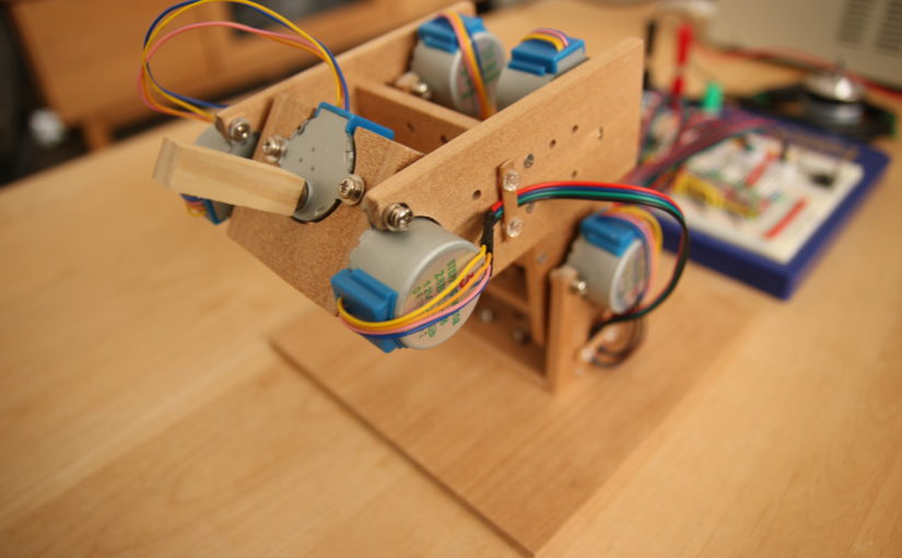
But is there good in the cheap? Can this 3 dollar stepper motor achieve greatness against all odds? No. But hey, it’s only 3 bucks, so you might as well get a dozen and see what you can come up with. I decided to throw the steppers at a simple robot arm project.
Driving the 28BYJ-48 with a A4988
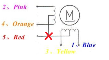
So what are some of the more interesting aspects of this robot arm? The first thing that comes to mind is the way the stepper motors are driven. I am using A4988 drivers on them. But it is only after you apply a small modification to the stepper motors inner wirings that you are able to do so. The 28BYJ-48’s are unipolar steppers. They need to be made into bipolar steppers for the A4988 to work. Basically, you just cut a connection.
But here’s a more informative blog post on how this is done.
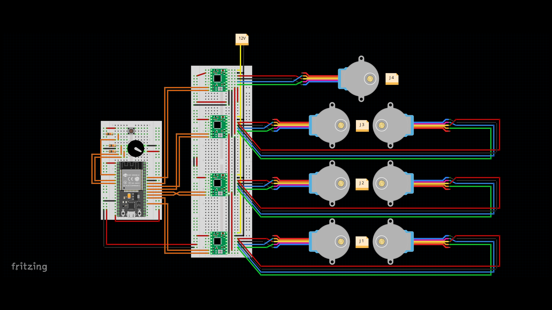
Above you can see the complete schematics of this project. Note how the red wire of the stepper motors isn’t connected to anything. That’s because after the above-mentioned procedure to turn the stepper from unipolar to bipolar there is no more use in this wire. The stepper turns from a 5-wire stepper into a 4-wire stepper.
But Why No Arduino?
Another interesting thing is this: I initially tried to get this robot arm to move with an Arduino. One goal was to make the movements as smooth as possible. So I was programming a library which was supposed to produce stepper pulses in such a way that the motors started and stopped very smoothly. I wanted the velocity curve to be sine shaped. So I implemented it, obviously, by using the sin() function. But the sin() function isn’t exactly a computational lightweight. It is quite the opposite in fact. The function uses a mathematical series to approximate a fairly accurate value of sin(x) for any input x that gets thrown at it. And it is all doubles. floating point operations are notorious for requiring many cycles on most Microprocessors. And the double, being the more accurate float, doesn’t make matters any better.
I wasn’t getting the performance I needed in order to move the steppers both smoothly and swiftly. So I did what seemed to be the most cost-effective solution: Switch to a faster microcontroller (the ESP32). Whilst the clock rate of most Arduinos is set to a rather modest 16 Mhz, the ESP32 boasts a 160MHz dual-core microprocessor.
After this switch, I was able to finish my smooth stepper-pulse-generator library without any further problems. I called it “SineStepper” and it is on Github, along with all the other code needed to run this robot arm:
Github: ESP32-MicroRobotArm
Solving The IK Equations
I also decided to implement the Inverse Kinematics calculations by myself. A fitting IK algorithm allows you to tell the robot arm where (in 3D space) you want its tip to point and the robot arm figures out all the details of how much to rotate which joint by itself. Here’s a sketch I made while thinking about how to solve them. The code solving the IK equations is in the RobotArmIK.ccp file on Github.
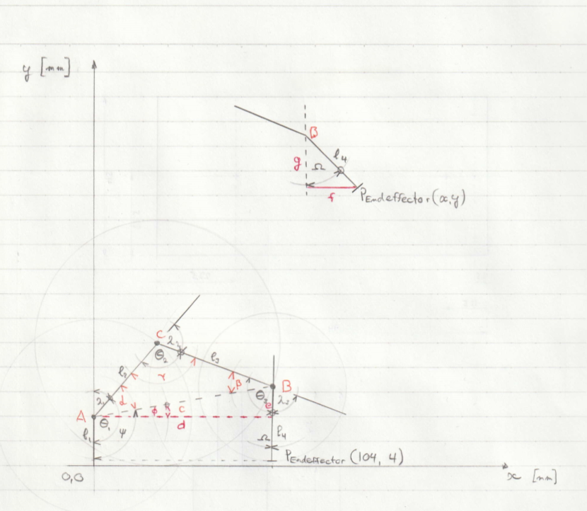
Because this robot arm is very simple (only 4 joints), the Inverse Kinematics can be solved analytically. This means that there’s a way to derive equations for how much each joint needs to rotate just by using trigonometry and analyzing how everything is connected. Here are some of the calculations.
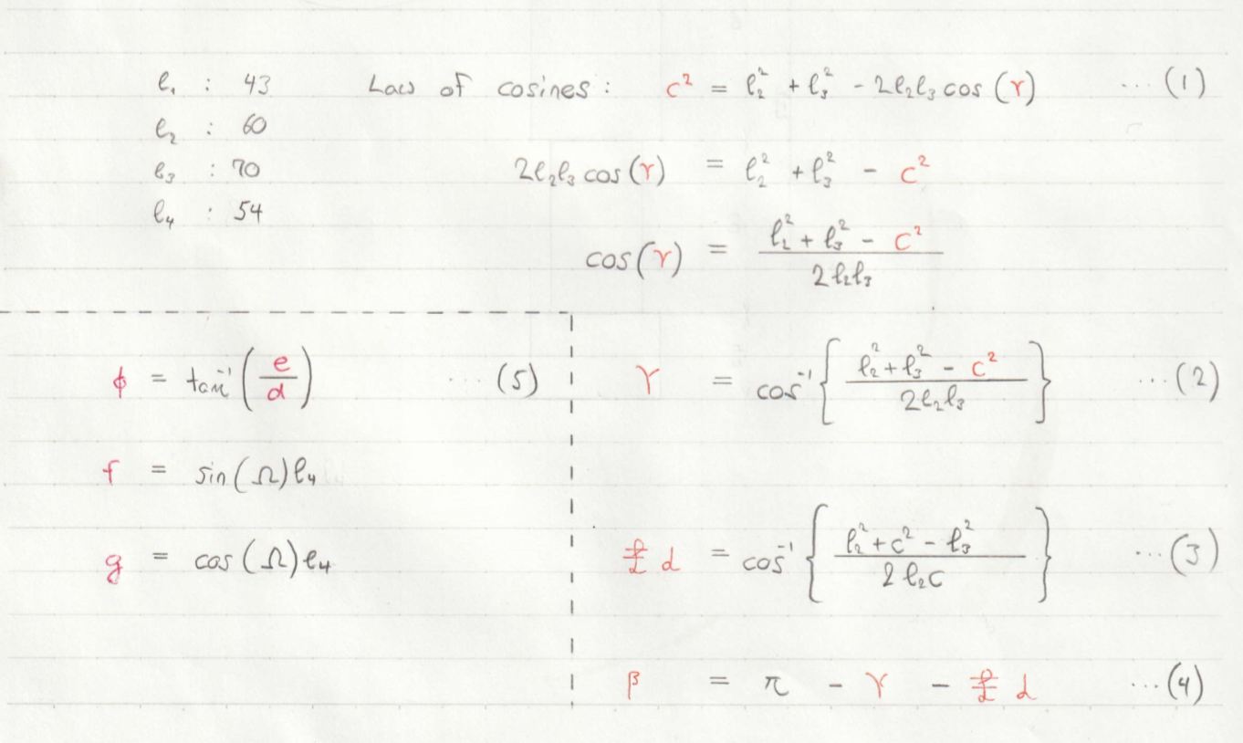
This can get way more complicated with more joints. Explaining the IK of this robot arm thoroughly and in such a way that it is easy to understand is a challenging task. It is something I’d like to try but I’d need more time to do it right. There might be another post in the future.
CAD Data
Another thing I challenged myself to do was the creation of 3D data. I used DesignSpark Mechanical 2.0 to create all the parts needed. I did that only after I actually finished the robot arm. But now that I got used to the software, I can see how it really should’ve been the other way around.
I uploaded the DesignSpark files here.
And since there’s an option to export the 3D models as .obj files, I just had to put them in Unity (a Game Engine I use at work). That’s how I ended up making a small assembly animation. The full animation is in the YouTube video I posted somewhere above.
Testing the precision
What are some good tests to apply to this robot arm? We want to figure out whether or not the thing is working the way we think it is working. For example, we think there are no missed steps, but is this really true? The robot arm operates open loop. There are no rotary encoders involved. The microcontroller keeps track of the current positions of all the joints by counting the pulses that are getting sent to the stepper driver chips. The motors might slip and lose a step. And even if the motors are moving reliably, is the microcontroller counting the steps correctly? There might be a bug in the software.
We need data. So let’s check how precise the robot arm is able to move. In the video below, the robot arm moves in a fixed manner. We mark 2 positions; One to check mainly for errors along the Y-Axis, another position for errors along the X-Axis.
The results show that the position used to check deviations along the Y-Axis got lower over time (the robot arm was moving for 5 minutes in total), while the error along the X-Axis seemed small. Since the error is in the same direction as the earth’s gravitational pull, this might indicate that there indeed were some missed steps. But one could also argue that the precision is within margins considering the gears backlash is about 2.5°. It also seemed like the error was converging to some certain amount.
More time had to be invested to pin down the cause/causes of the error seen in this video. Since it is moving fairly accurate I call it a day. The next project’s waiting!
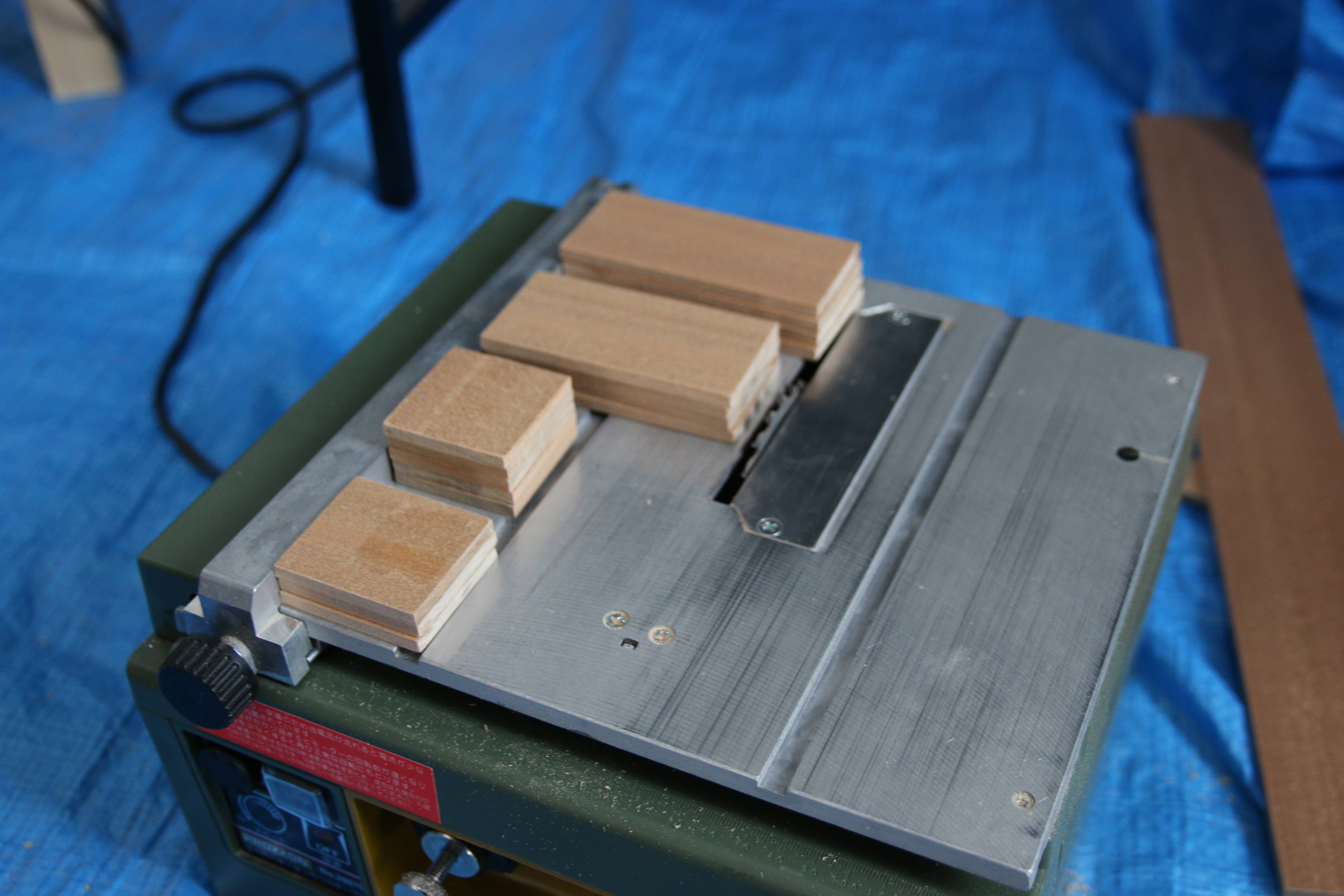
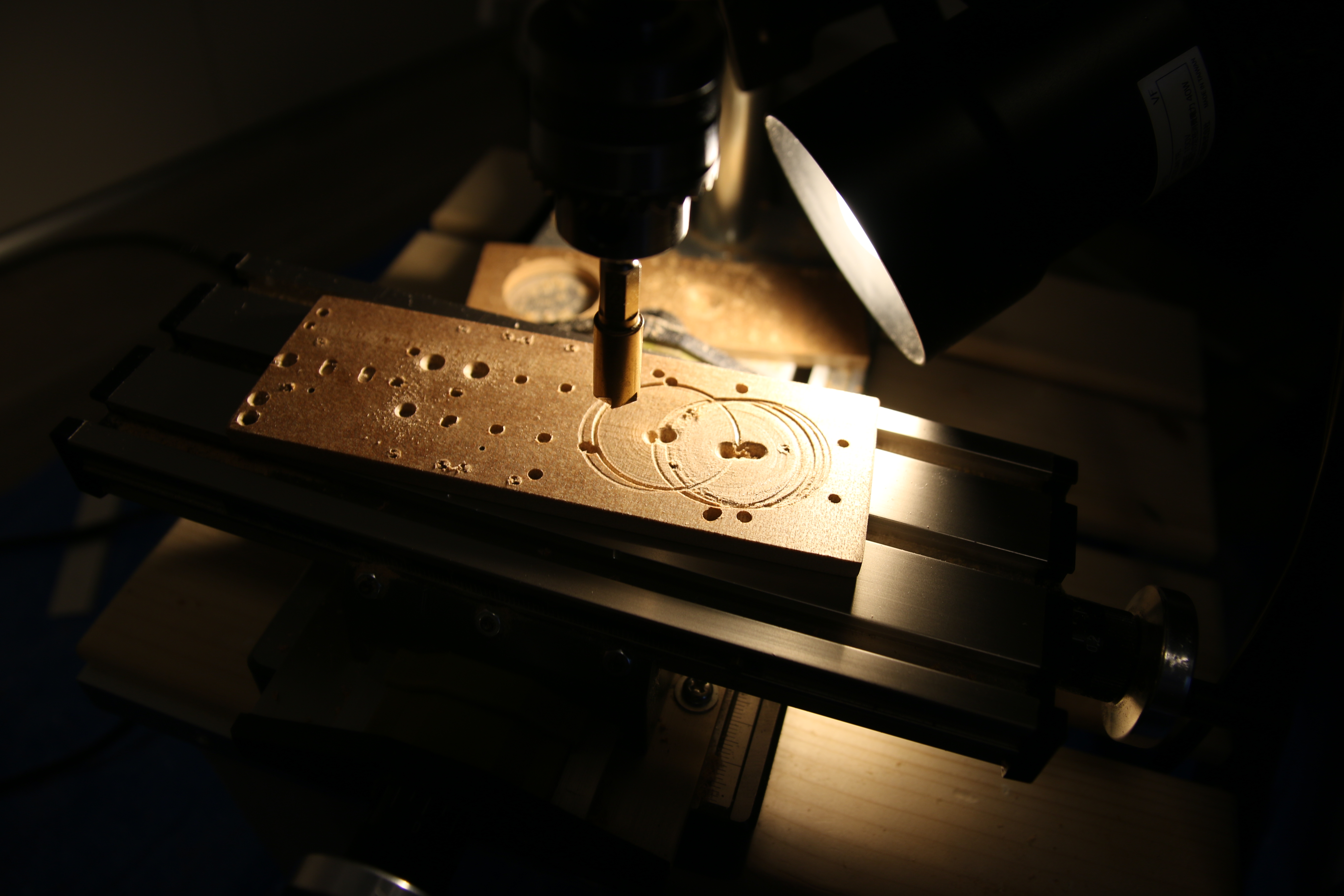
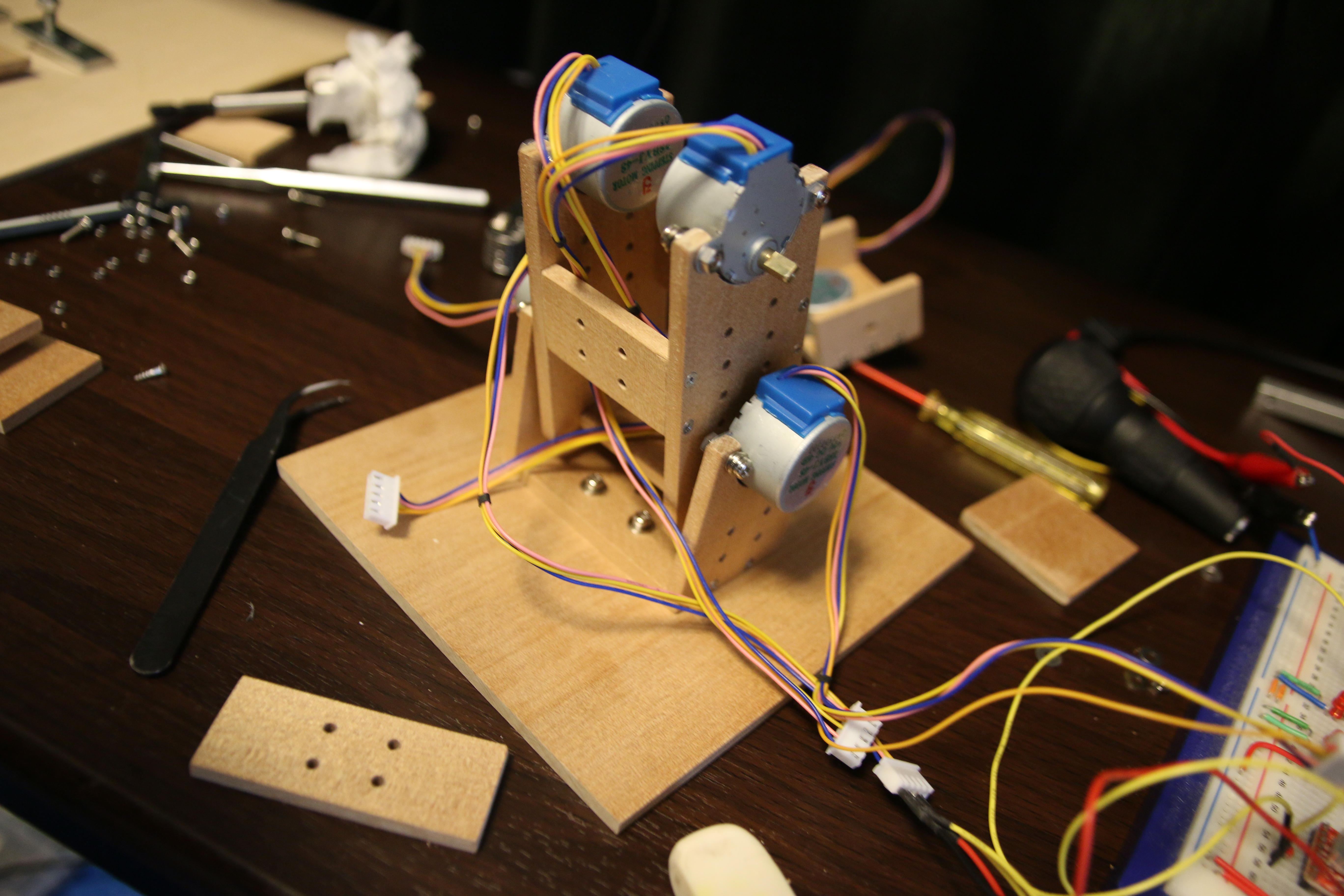
Building the ESP32 Micro Robot Arm
Here are some pictures I took while building the robot arm.
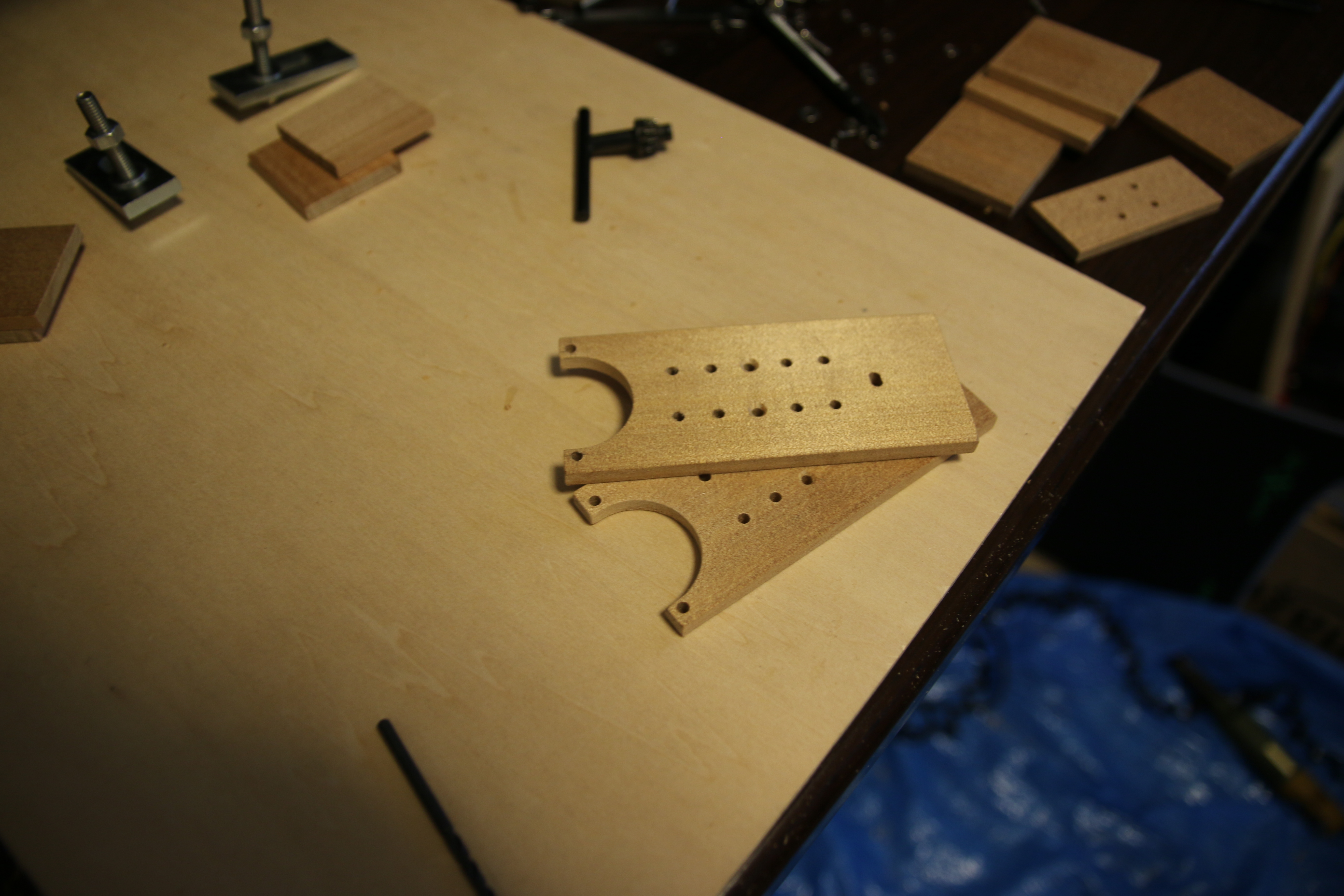
Mechanical Parts
Here are all the parts you need to produce in order to assemble this Robot Arm.
Link1 (2 pieces)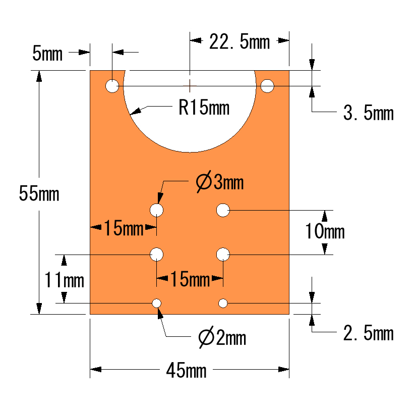
Link1 Spacer (1 piece)![]()
Link2 (2 pieces)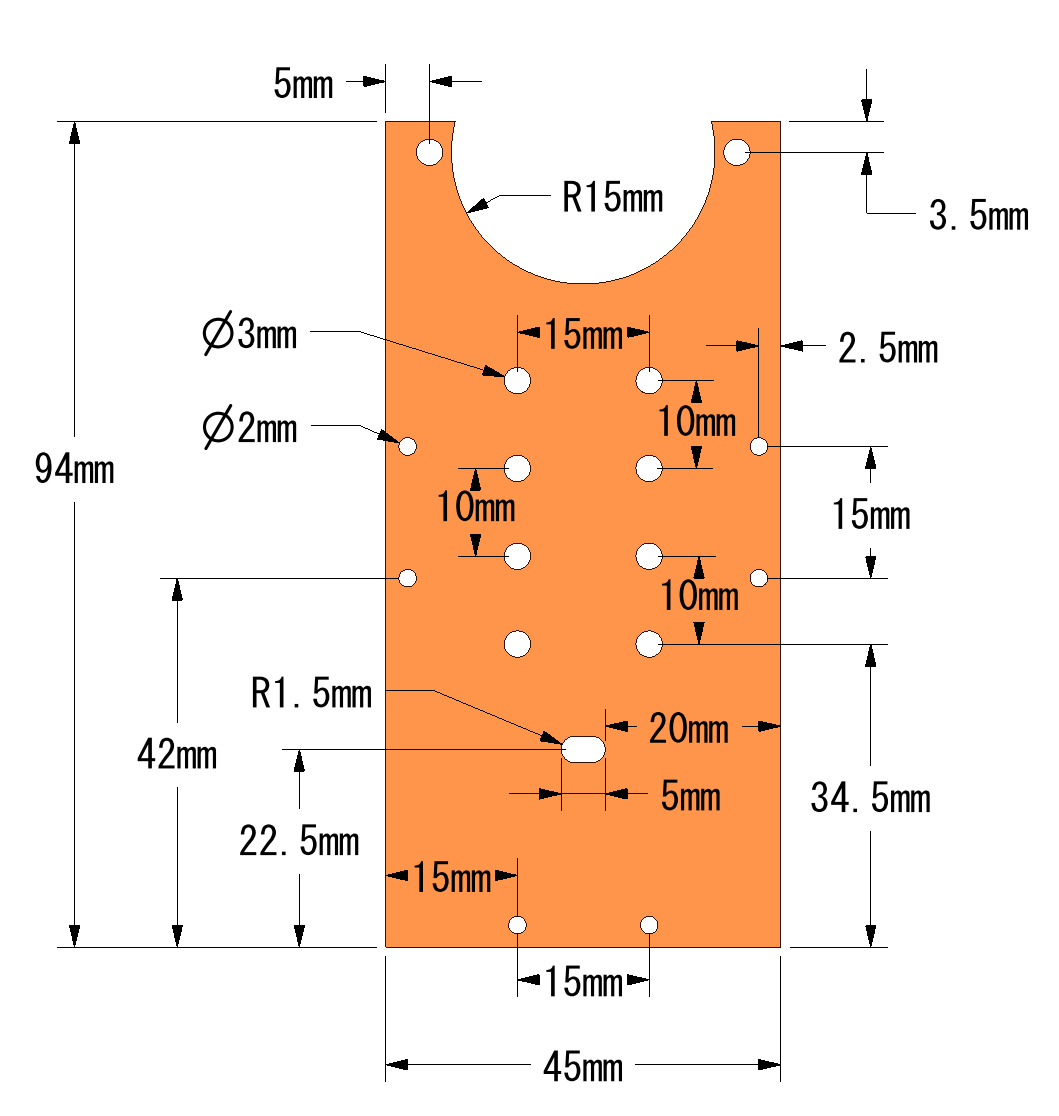
Link2 Spacer (3 pieces)![]()
Link3 (2 pieces)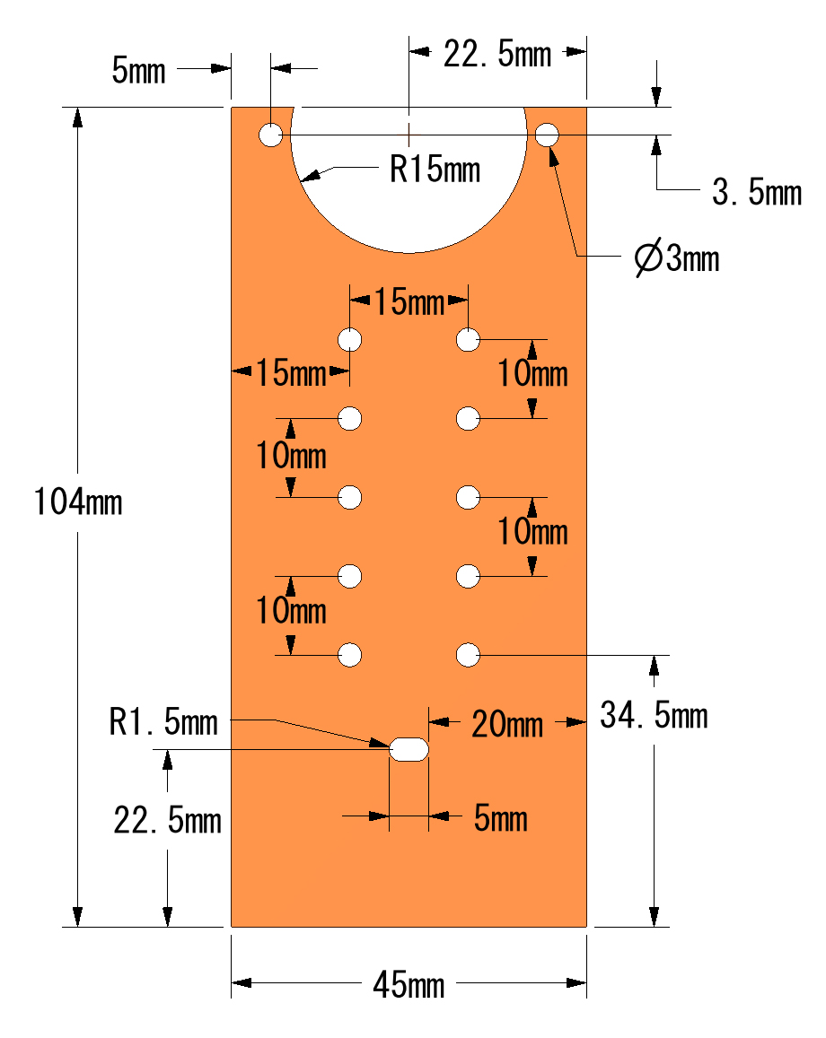
Link3 Spacer (1 piece)![]()
Link4 (2 pieces)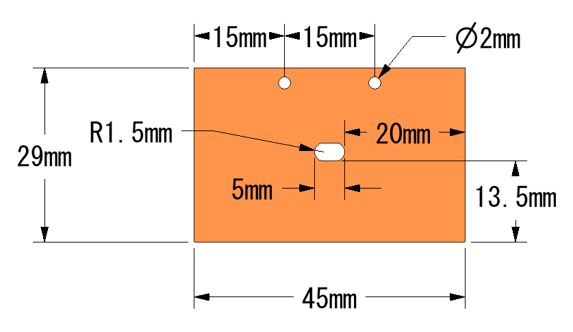 Link4 Spacer (1 piece)
![]()
Tip (1 piece)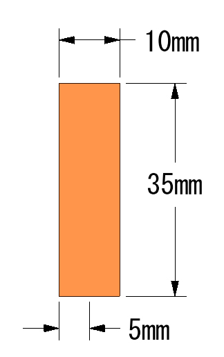 I wrote an instructable about this project. Check it out here!
Hi T-Kuhn,
a fascinating project – I assume you are using two stepper motors per axis to increase the torque? It is an interesting approach 🙂
This post in very interesting to me as I am currently working on a project using ROS to manage an autonomous robot that is supposed to be able to grip lightweight stuff with a robotic arm and I aim to test my code using a smaller copy of it (without the need to spend a fortune on parts). Thank you very much for sharing your experiences!
Kind regards,
Alex
Hi Alex,
Thanks for the comment and all the best for your project!
Your project is good . Do you have interest in making PCB project ? We can sponsor you free PCB you want .
Please feel free to contact me if you have any inetrest .
Hello,
We are interested in partnering with you. We are an International Technology Marketplace based out of New York. We partner with Tech Companies to resell their products including Robotics, Drones, 3D Printers, Machinery, and Software on Oz Robotics. com. Upon your reply, we will send you our proposal that outlines the process.
We look forward to hearing from you about a possible partnership.
Best Regards,
Errol Oz | Founder and CEO
If you have already responded, please ignore this email. Thank you.
This is a one-time email. The writing in this letter is privileged for the individual and/or entity identified in the alias of this letter. If the reader of this letter is not the right person then please deliver it to the appropriate staff. If you have received this communication in error, please notify us by replying to this email. Thank you.
hi
you could help me to understand why I get errors when I check the shacth on arduino?
This project uses a ESP32. You might need to set up the Arduino IDE in order to be able to program that type of microcontroller:
https://github.com/espressif/arduino-esp32/blob/master/docs/arduino-ide/boards_manager.md
thanks for your reply and the time you dedicated me
In addition I wanted to tell you that the current error is the following “hw_timer_t ‘does a tipe”
cards installed. Error “buttoncoolDownCounter” was not declared in this scope
😢
Hello, Mr. T-Kuhn, I have a project to complete a technical course in my high school in Brazil and I was interested in the way you controlled your arm, I would very much like to apply it on my arm to learn a little about esp32, but I am with problem for the circuit available for the protoboard. Would you like to provide the circuit for modification in the fritizing or some image with indication of the pins of esp32 and a4988? because I have difficulty locating the correct pins, because in the image of the fritzing they are not indicated and my connections turn out wrong. Congratulations on the great project and thank you for making this material available, the people of my robotic group here in Brazil are studying a lot about it so that it can reach more people. Thank you.
Hello Abner Vicente,
Thanks for reaching out. I do not have a schematics with all the pin numbers, but here is how to figure this out:
1. Go here to read about what the output pins are doing:
https://github.com/T-Kuhn/ESP32-MicroRobotArm/blob/master/MicroRobotArm/Constants.h
For example, “BUTTON_PIN 34” means there’s a button connected to GPIO 34.
2. Google “ESP32 pin out” and take a look at the pictures. You should find pics with the GPIO numbers of each pin. This way you are able to find out where GPIO 34 is.
3. The same works for the A4988, google “A4988 pin out” and you should be able to figure out how it works.
I am sorry that I can not offer a better schematics. I hope this comment helps. Just ask again if there’s anything you need to know.
Good luck!
which software to control this robot arm?
It’s just embedded code for the ESP32. It’s over here:
https://github.com/T-Kuhn/ESP32-MicroRobotArm
Hello, thank you very much for this tutorial, I built the robot and it looks great! Can you please provide a piece of sample code that would test if I have the pinout set correctly in the code (ex. Link 4 being the top motor) to do very small movements? I’m having trouble running the code as the robot flops over and falls, but I have not been able to pinpoint to whether this is from the way that I assembled it or if it is from the links that I chose for each motor in the code. Again, thank you very much.
Hi,
Nice work! It seems like you’re almost there. Just a little more debugging and you’ll have the Robot Arm moving around.
Here are some pointers:
1. I updated the program on Github: https://github.com/T-Kuhn/ESP32-MicroRobotArm
If you load this newest version onto the ESP32 via Arduino IDE with ESP32 plugin the robot should move exactly like it does in this video:
https://www.youtube.com/watch?v=twJG0otS8CI
Are you also using the rotary encoder and switch as shown in the schematics? If so you’ll get the chance to go through the calibration process (and you in fact have to to get to the part where the arm will move around automatically.) Just move the shaft of the rotary encoder to calibrate each link one at a time in such a way that the robot arm is standing upright. after you’re done with a link press the button to continue with the nect link. After you’re through with all of them the repeatability test program will start and the robot arm should move exactly as the one in the video linked above.
2. Are you interfacing the A4988 chip exactly as shown in the schematics? If you’re motors seem to be running too fast, check the schematics (especially the pins concerning microstep resolution)
Hope this will help you in some way or another. Keep on going and share you’re result with the world once you’re done!
Hellk sir
May i know why we need stepper motor, on both end of a joint.(for your information i didnt try the project, just curious to know, the additional benefit of using two motors on the joint).☺️
Hello
I am looking up the 28BYJ_48 on amazon , and they come with their own driver unlike the one you have on the schematic I am wonderingg if they would work aswell. I attached the link in this comment. I would also like to ask which type of arduino did you use to code the ESP32 , Uno , mega ?
Thanks
I just realized you are using 12V 28BYJ, would it be any different using the 5V version, I am using a 3d printer to make the arm parts it will be much lighter.
Hi Adam,
The 5V version should work just fine, though you might not get quite as much rpm out of it because higher rpms are possible with higher voltage.
My 12V 28BYJ also came with a driver. You can use that driver, but you might want to change the wiring of your 28BYJ in order to run it as a bipolar stepper motor. Bipolar stepper motors can be driven with the A4988 driver. Your 28BYJ stepper motor will have more torque after changing it to bipolar and using the A4988 driver chip. Here’s how to change the wiring in order to make it a bipolar stepper motor:
http://www.jangeox.be/2013/10/change-unipolar-28byj-48-to-bipolar.html
I used no Arduino to code the ESP-32. I used the ESP-32 microcontroller instead of an Arduino. The coding and flashing was done with the Arduino IDE using the ESP-32 plugin. See here for more information:
https://github.com/espressif/arduino-esp32/blob/master/docs/arduino-ide/boards_manager.md
How do you program this robot arm ?
With arduino or what program ?
I have an idea and i want to know how can i program different positions and make an infinite loop.
For example, the robot arm would organize or transport little boxes from a conveyor band to other conveyor band do you undertand what i mean ?
Ohh man you are awesome !!!
Please can you help me ? i want to show your project to all my school !! pleaseeeeee
How much amp does one Stepper use?
Ok, so I watched the whole thing… read everything and researched the hell out of everything I could find on the motors, then went ahead and ordered a bunch of 28byj-48, a4988s, ramps 1.4, pulleys, belts, worm gears, couplers, and the whole deal… gonna implement them in a bunch of projects, but a couple things I would love to get you 2cents on:
1) after the bipolar conversation, do you know what’s the max speed/rpm and torque you get? Couldn’t find a definite data.
2) as someone previously asked, are you using dual drive system? Meaning are the two parallel motors on the arm are eventually responsible for sharing the load and axial movement?
Gotta say that your project got me looking into testing some more cheap commonly used yet underappreciated electronics and the potential reusability for other everyday aspects.
Thank you so much for documenting, sharing and making.
Sincerely,
Eyal cohen
Hey Eyal,
1) I don’t know either. I made no measurements or comparisons.
2) Yes, the idea was to have the load evenly distributed along the two motors. I did use a common driver for the two motors of each joint. This doesn’t need to be that way necessarily but it felt like the right thing to do considering that those A4988 drivers are delivering up to 1 A of current.
Hello thank you for the free plannes of this robot.
I make my one version of the robot with the cnc shield.
This wil be an example for my student to draw one in inventor or fusin 360.
https://www.youtube.com/watch?v=Z65FRT5Ergw
My robot is not working so well as yours, next robot I will try with teh esp 32 like yours.
Nice assembly animation in that YouTube video!
In addition I wanted to tell you that the current error is the following “hw_timer_t ‘does a tipe”
‘timerMux’ was not declared in this scope
Hi
it’s very interesting project
I’d like to speak to you by Skype, Whatsapp, etc.
Thanks a lot
Projeto excelente,
Estou com dificuldades em entender o código, não consigo achar a sequencia lógica do funcionamento do braço.
Excellent design,
I’m having trouble understanding the code, I can’t find the logical sequence of how the arm works.
If you were using 5v steppers instead of 12v ones, would you still use a 12v power supply?
I created this with 3d printed parts and used an Arduino instead. Amazing project!
Hi
This is a great project and I’ve learnt a lot already. I’m trying to replicate the diagrams to produce stl files. I’m having trouble with working out the exact dimensions in at least one of them. The one I’m having trouble with is ‘Link4 Spacer ‘.
I can’t deduce the length of the gap on the top of the R15 circle. Do you know it?
Length of the gap should be 7.5mm.