This entry is about the quest to get a machine to juggle a ping pong ball.
I started thinking about a ping pong ball juggler 2 years ago. And it was around that time that I built the first one of them. it uses LED – Photo transistor pairs to “see” when and approximately where the ball comes down. I used 4 micro servos to move a wooden plate. It’s the machine in the first YouTube video.
The next major update came when I decided it might be interesting to try to track the balls position by using the noise the ball makes when it hits the plate. I installed 4 mics and switched a FlipFlop on as soon as the sound level got over some threshold. The FlipFlop’s value then gets read by a micro controller as fast as possible to then compute the time difference between the sound waves hitting the mic on the left in comparison to the mic on the right. The same goes for the front and back mics. This way 2 dimensional data about the ball position is gathered. It worked quite well.
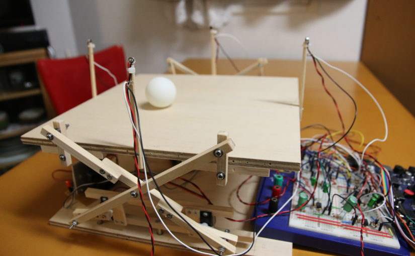
I also updated the scissor like x-shaped thing. I went from using chopsticks to home center wood. I didn’t use ball bearings on the joints though. That’s one thing that would’ve improved the performance I think. The machine on this stage is the one in the second YouTube video.
Yet Another Version…?
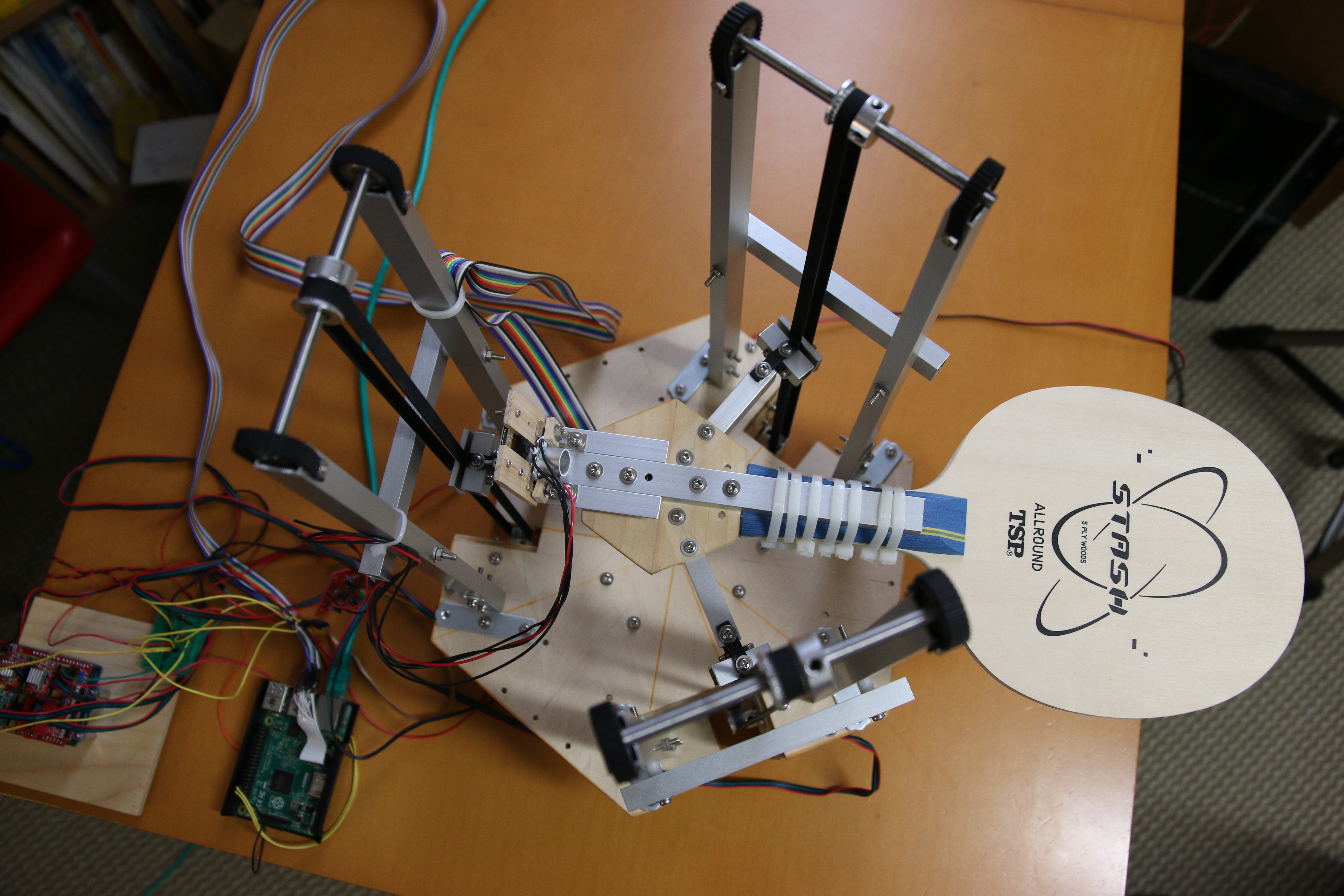
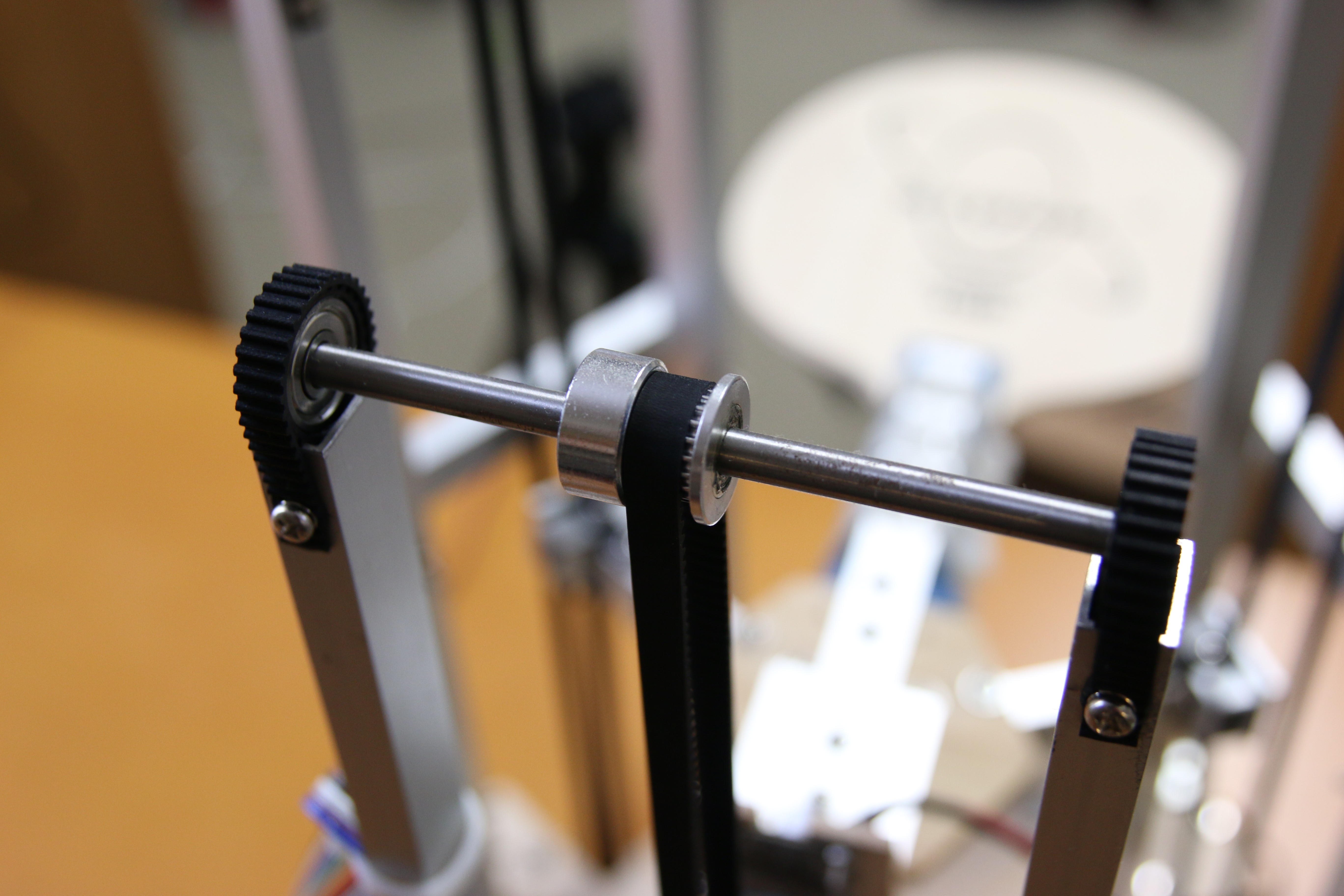
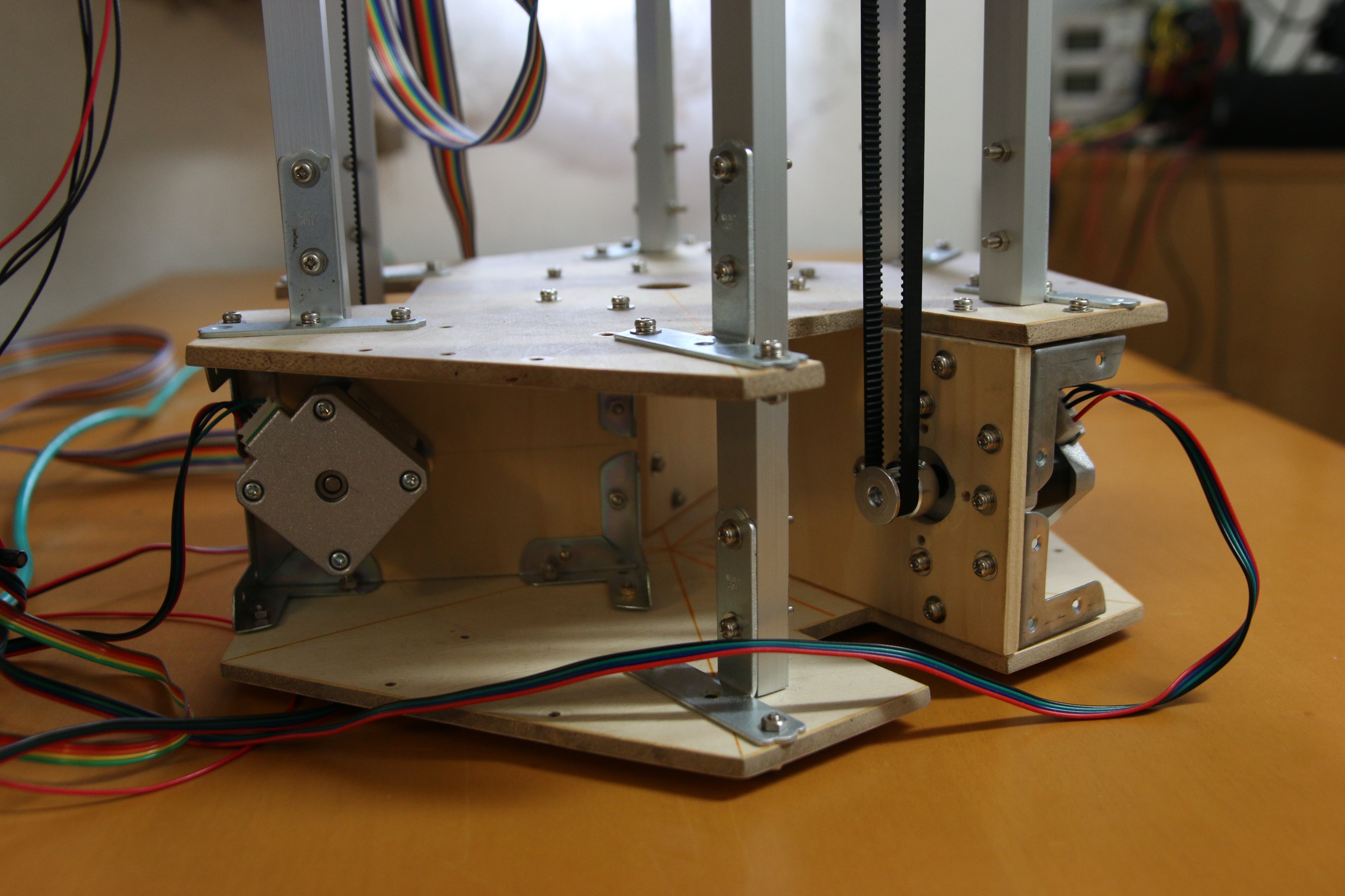
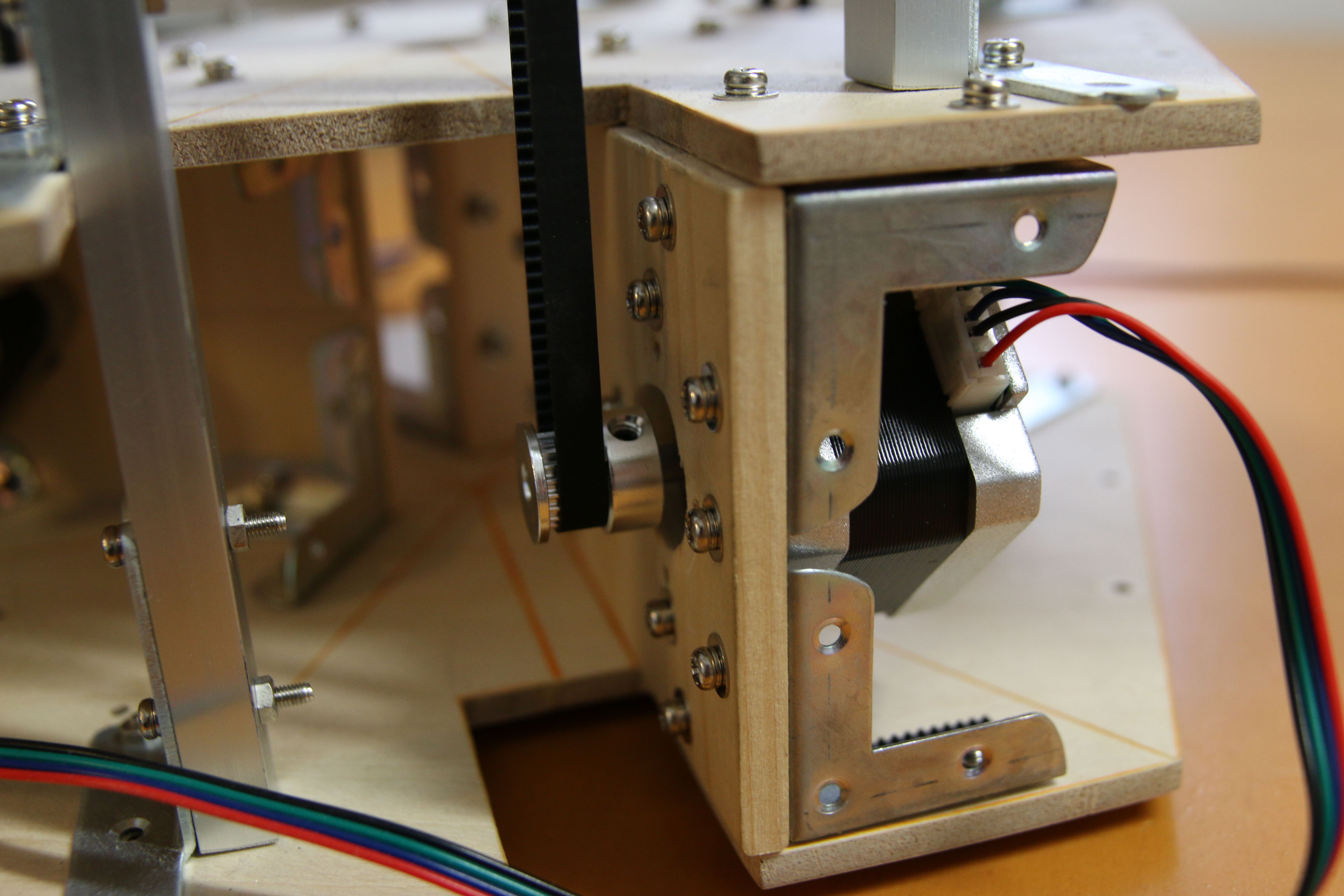
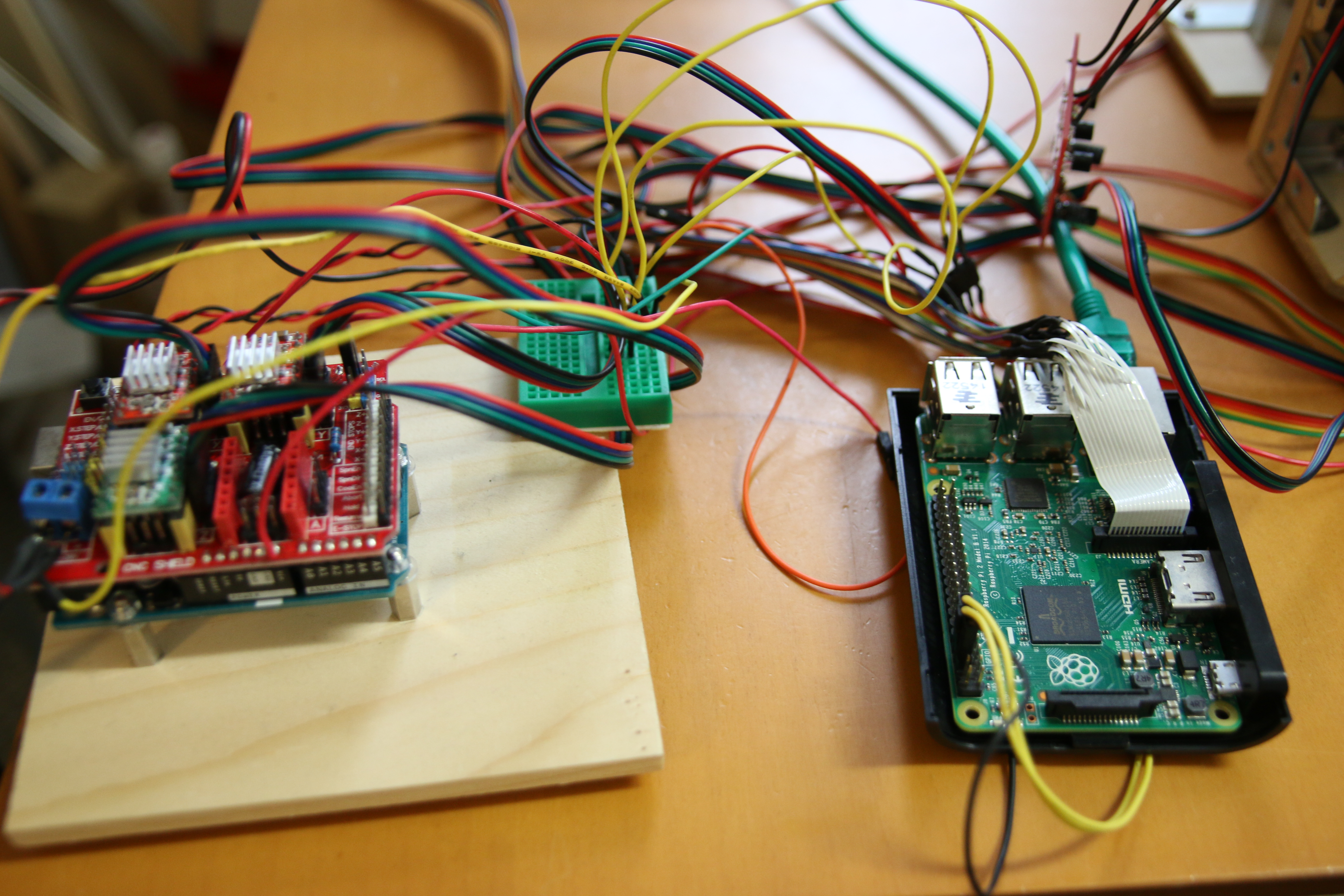
After that I did other things for a long time. But some months ago I wanted to rebuild the machine from scratch. This entry is about this rebuilt version. The 2 videos on the top are just meant for a quick history on how it started. So, what changed? I no longer use servos but Nema17 stepper motors for the movements. I bought some belt drive components and ball bearings. I used those to convert the axial motion of the steppers into linear motion. It’s the same setup as in an inkjet printer.
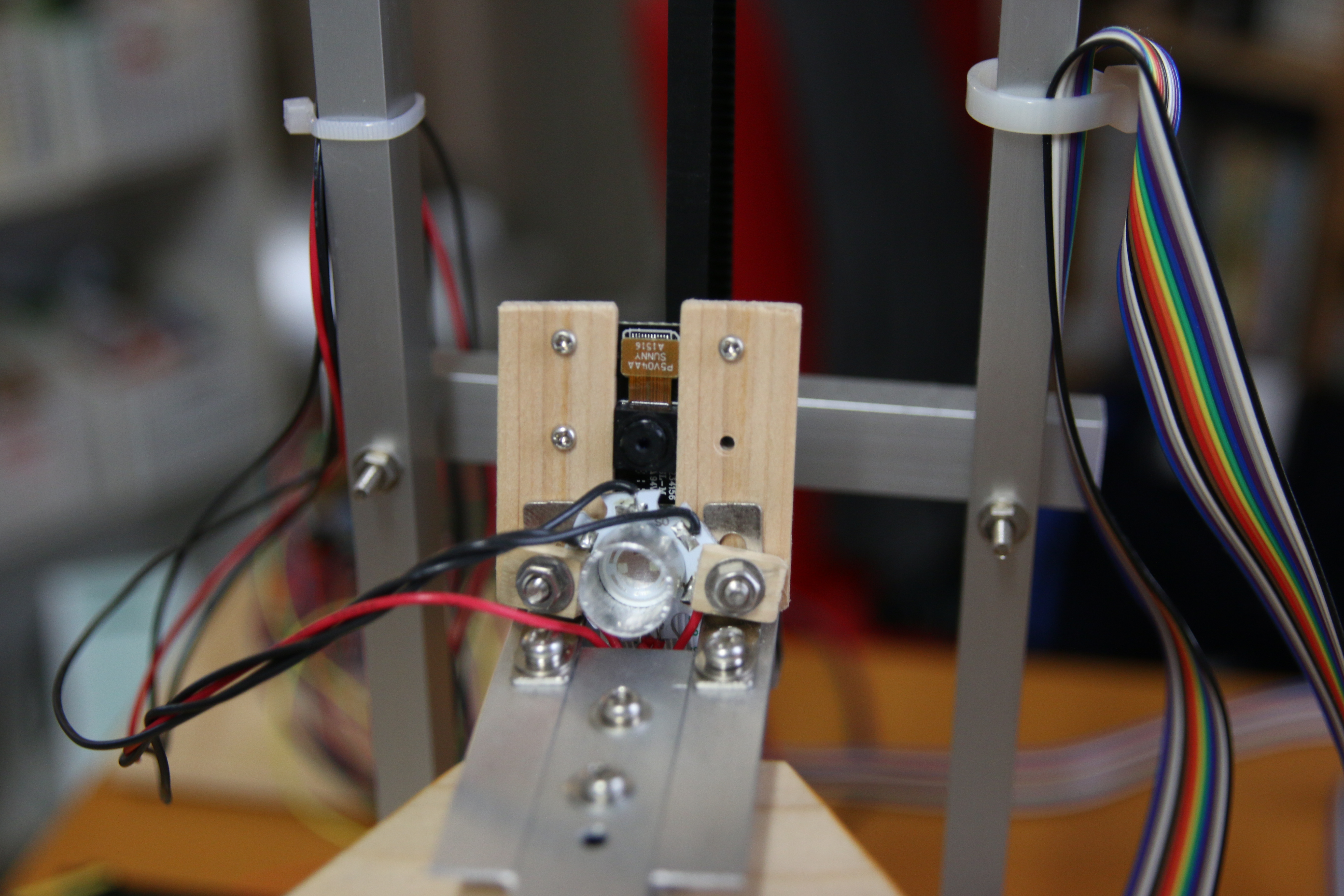
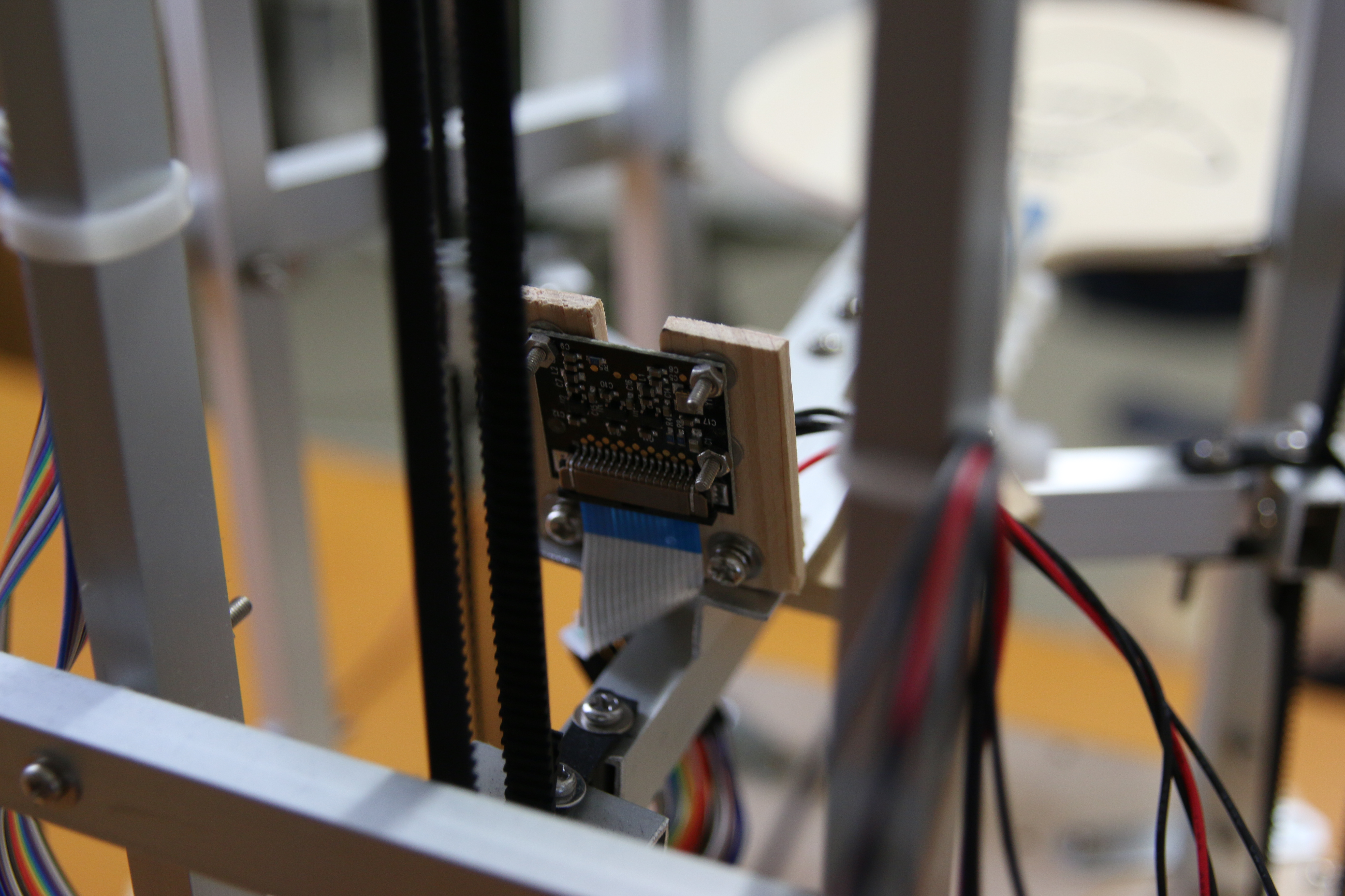
The main controller of this project is a Raspberry Pi 2. It has a Raspberry Pi camera module NoIR connected to it. Because it is NoIR, there’s no IR filter on the thing. I originally planned to use infrared light to brighten up the ball in front of the camera. But it didn’t work well. The IR elements I used were way to weak. The infrared noise in the background (sunlight etc.) would overweight the infrared light getting reflected from the ball. Another problem was, that the IR signal gets picked up on the red-channel of the camera. This means that even if there is no infrared noise from sunlight, the infrared light’s intensity still has to surpass the normal red light’s intensity to be recognizable. So that idea got dropped. I ended up using the green-channel on the camera with green light from a RGB Power LED pointed at the ping pong ball. Sure enough, normal white light would’ve done the job as well, but I just happened to have a RGB LED laying around so I ended up with green.
Some Words On The Image Processing
Another important thing is this: You might be asking yourself “Why did you use a light source anyway? Couldn’t you just use OpenCV and get the thing to recognize the white ball with normal lightning conditions?”. The answer to this is: Probably not. At least not with a Raspberry Pi 2. The reason being that we need 90 fps real time image processing to track that ball. The image processing has to be done fast. I didn’t really use OpenCV for anything at this Point in time but my guess is, that it wouldn’t work well, because I don’t think I could get the processing rate up to 90 fps with OpenCV. Maybe I am wrong about this, but it was my gut feeling, so I went on to program a really simple algorithm that could take care of the image data really fast. The algorithm looks directly at the data stream, so no conversion to a different datatype (e.g. NumPy) is needed. This is one reason this algorithm is quite fast. The other reason is, of course, that it is a dumb algorithm. All it does is look for a clump of bright green pixels on a fairly black background and then compute the center of it.
After the algorithm extracted 3D coordinates out of the images it examines that data and, in the case the ball is going downwards and gets quite near to the racket, it uses that specific data set in a PID controller to get some useful correction values on the racket as the ball is moving towards it (the machine tries to get the ball into the center of the racket). The movement values are then sent to the Arduino Uno over the serial port. The Arduino Uno runs grbl (a program for running stepper motors very efficiently) and all it does most of the time is waiting for some new instructions from it’s master; The Raspberry Pi.
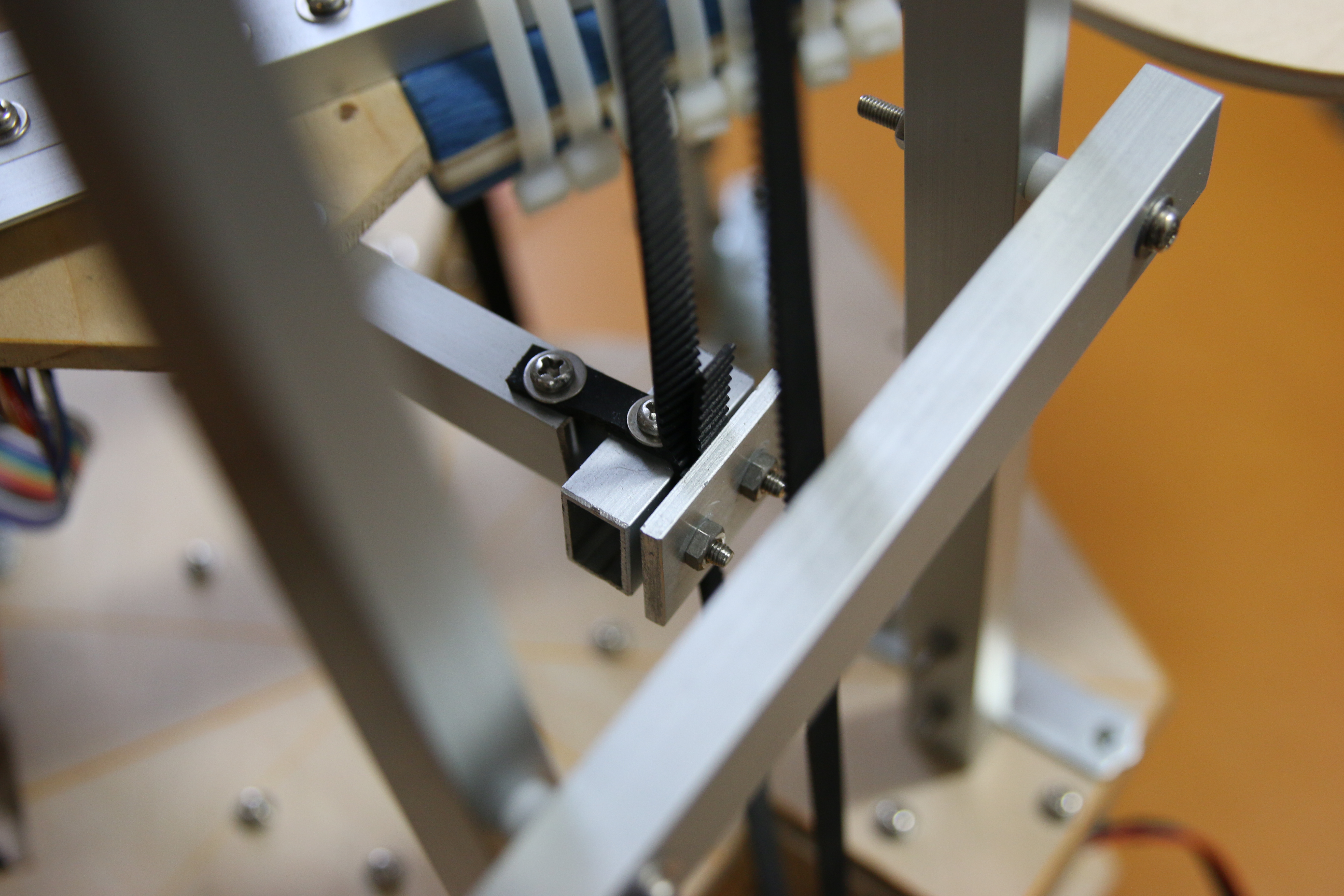
Some lines about the tilting mechanism: The tilt in the racket is produced by different heights of the 3 belts on which the racket is mounted. The joint “belt to racket” is a rather elastic one. This is why a tilted racket can be accomplished without ruining the joints or other parts of the machine.
Some Afterthoughts
It’s worth mentioning that the thing isn’t working perfectly at all. A 2 hour juggling session is definite not one of the things this machine is capable of doing. It is able to juggle the ball for about 2 mins. Then it makes some misjudgment and the ball drops. So it isn’t great. But then again: It only uses one single camera to compute 3D coordinates of a flying object. using 2 cameras would improve the performance. But it would also make the thing more complicated.
Here are some pics of the machine:
GIFs of the Juggling Motion
And here some GIFs made from image data of the Raspberry Pi camera module:
This gif was made in the very early stages of this project. It was made to check if the ball in the image data looks crisp enough to allow an image processing algorithm to extract the ball position from it.
Here is some image data of actual ball juggling. The red light was put there to make the racket movements visible. The grid represents points at which the algorithm checks for pixel brigthness. If the value on a gridpoint is bright enough the algorithm computes the center of the clump of bright pixels at that specific position (this data is used as x and y coordinates). The z coordinate is extracted from the width of the diameter of the ball.
Here’s the Raspberry Pi 2 Python code:
https://github.com/T-Kuhn/PingPongPi
And Here’s the superb grbl code (the thing running on the Arduino Uno):
https://github.com/gnea/grbl
Awesome idea and project evolution!
Got a question on how you deal with mic signal.
How do you implement FFT? How do you determine your sampling frequency and buffer size so that the sound of ping pong ball can be captured and the time difference can be clearly calculated.
Thanks!
Hi Jason,
> How do you implement FFT?
I didn’t. I used an analog circuit with a Flip-Flop attached to it for each mic. The analog circuit handles high pass filtering and passes the analog signal to a Schmitt trigger kind of circuit (I actually just used a Flip-Flop with some diodes to adjust the voltages level for it to switch on). As you see, I wasn’t looking for specific frequencies but rather for any loud sound. But it worked quite nicely. It wouldn’t falsely detect human voice as a ball drop since the sharp ball drop spikes are way more prominent than the casual talking voice ever would get.
After setting one Flip-Flop per mic, I used a microcontroller to read all the Flip-Flop states in at once. I did that in fast succession and counted the cycle count between Flip-Flops getting set into the high-state. From that data, I calculated the 2-dimensional position the ball was hitting the plate.
Nice post. Thanks for sharing it.
great idea!
how long it took you to finish each stage?