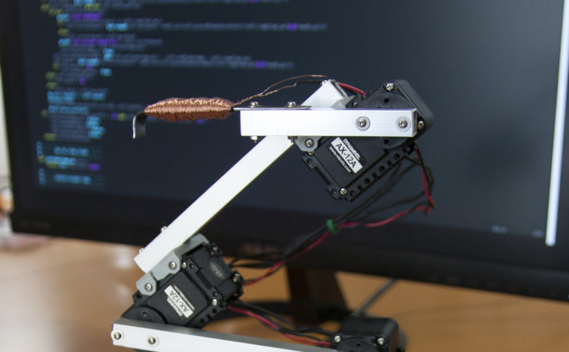
This entry is about a small Raspberry Pi robot arm I made more then a year ago. I used Dynamixel AX-12A servos. They are quite expensive. But the rule “I payed more so it ought to be better” applies; What you get are very easily configurable strong smart servos. The “smart” just meaning that you can control them via serial bus.
So let’s go over some specs. The robot arm is made of:
- 4 Dynamixel AX-12A servos
- 1 Raspberry Pi 2 model B
- 1 Raspberry Pi camera module
- 1 Electromagnet on the top
- Aluminum, wood
- A small circuit for communicating with the servos (see here for more info’s)
- Colorful ribbon cables
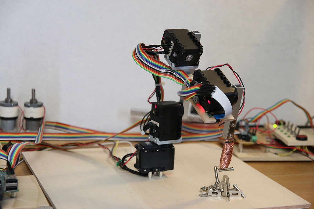
This Raspberry Pi robot arm is able to search for screws (image processing with the Raspberry Pi camera module), pick them up and put them somewhere. Things I tried to optimize while building the thing are as follows:
- Making it move smoothly
- Getting it to pick up screws consistently
Making it move smoothly
I wasn’t satisfied with the servos moving around when given just the goal position. The stopping and starting was too harsh, too sudden. The robot arm was shaking after reaching its goal position. I tried to fix this by implementing a software start-stop controller. Given a goal position, it makes sure that both the starts and stops are shaped in the form of a sine wave. This was supposed to make it move more elegantly, more smoothly. And to a certain degree, it works. For the case you are wondering how the heck the speed control was done more specifically: “speed” is one of the servos parameters which can be controlled over the serial bus. It is as easy as that. No need to try to get some kind of current control going. The servo does it all for you.
Getting it to pick up screws consistently
The second thing worth mentioning is the image processing. I didn’t use OpenCV. The image processing algorithms applied here are all very simple. I wanted to write them by my own. An important library which I used was pythons “picamera”. “picamera” provides an easy way to get grey scale pixel data from the Raspberry Pi camera module. The pixel data then was put through some algorithms: Edge Detection, Binarization, Pixel Expansion, Labeling and Object Extraction. After that, the robot knows the positions of the objects in front of it (only in the xy plane though) and it’s area in pixels. The area is useful when deciding whether or not to pick up objects. This Raspberry Pi robot arm will ignore things if they appear to be too small.
So let’s take a closer look at the image processing. I wrote that I used several algorithms to determine the xy position of the screws. I called the algorithms Edge Detection, Binarization, Pixel Expansion, Labeling and Object Extraction. But what do those names mean? What are the algorithms doing? The gif below shows how the image data gets altered by those algorithms in the same order.
Starting with the gray scale image the data gets processed and passed to the next algorithm. In the end, all that’s left are 3 points which determine the 2 dimensional position of the objects when viewed from the camera. Note how the objects differ in color. Different colors mean the Raspberry Pi is aware that there are multiple objects on the table. Watch the embedded video above to see more image processing pics (they are in the second half of the video). 
Moving the robot arm to reach the target
What do we got so far? We got an image with some objects on it. We used some simple image processing algorithms to extract the xy position relative to the camera. Notice how the units for this coordinate are literally “pixels”. We could determine some constant to compute the position in [cm], [inches], or any other unity of length we desire, but this all means nothing to the Raspberry Pi, so we might as well leave it the way it is. Our unit of length at this point is the [pixel].
What’s next? We need a way to move the robot arm in such a way that the electromagnet tip comes close enough to the object so that we can pick it up. There are several ways to do this. Here are two ideas which might pop up.
- Inverse kinematics
- Path teaching
The idea with the former approach is that we let the program know about how long all the parts of the Raspberry Pi robot arm are and how they are connected. This, plus the information about the rotation of all the joints relative to each other enables the Raspberry Pi to figure out how much and in which direction every joint has to be rotated to reach any point within the working area. By any point I mean any point in 3 dimensional space around the robot arm. This is the sophisticated way to do it. I, however, chose another path.
The Path Teaching Approach
I went for the lazy way. The path teaching way. For the specific problem of picking up screws with an electromagnet, this approach is actually not as horrible as you might expect. The electromagnet enables us to pick up screws even if we aren’t quite at the right position. But I am getting ahead of myself. So how did we implement path teaching in this project? Take a look at the image below.
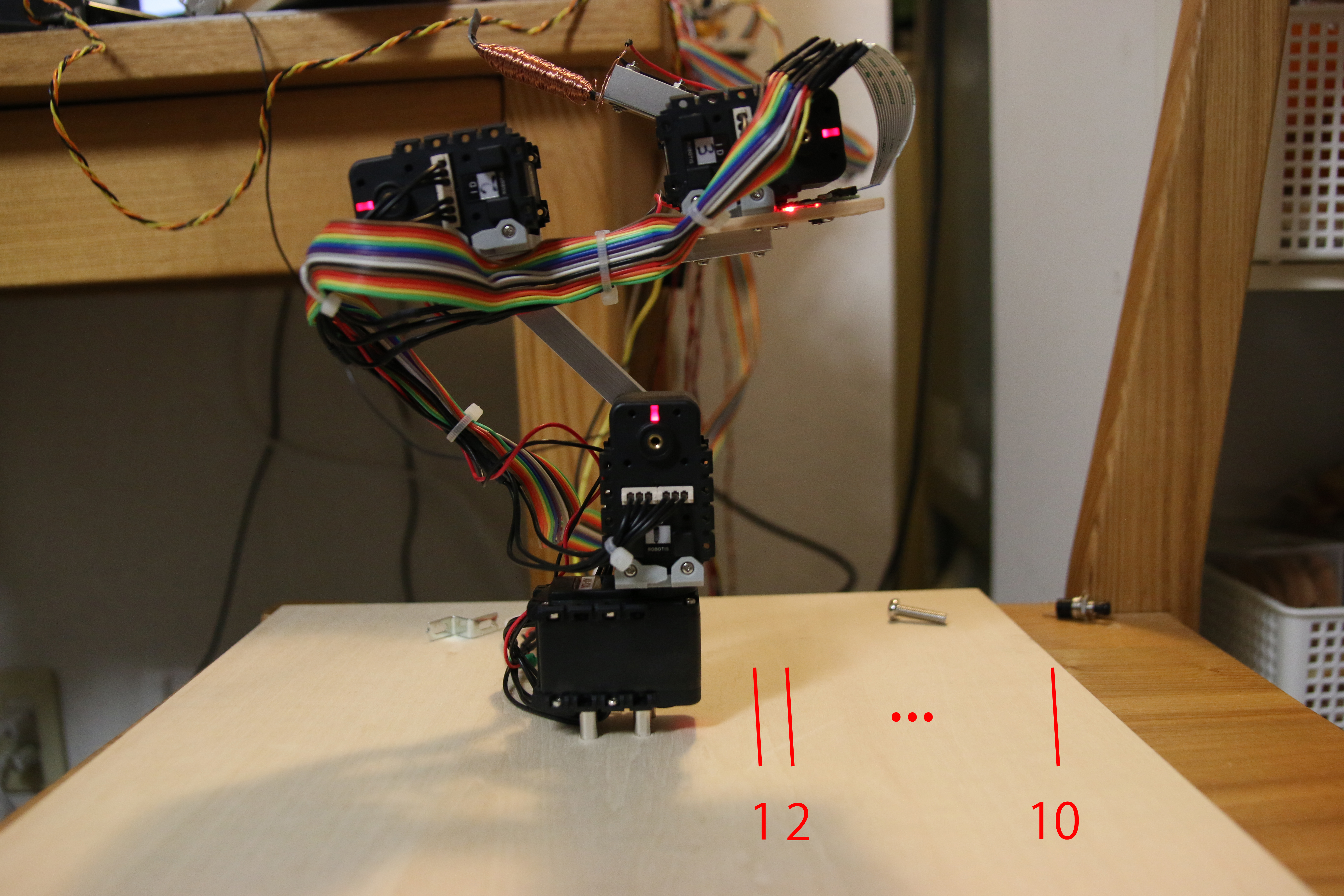
We separated the space in front of the robot arm in to 10 segments. Each segment is depicted by a line. Segment 10 is the furthest away – going back to the pixel data it translates to an object with a very high number of pixels in the y direction (the height of the image, when looked at on a screen). Now all we need to do is to teach the Raspberry Pi robot arm 10 different movement sequences to reach those 10 segments individually. Each sequence consisting of an array with rotation values for the 4 different joints. It doesn’t matter how or in which order the joints move – as long as the Raspberry Pi robot arm won’t destroy itself in the process and the electromagnet will point at the designated segment after we are done with the sequence.
But how about the x direction? The answer is quite simple: We just rotate the hole Arm. The amount can be determined by multiplying the pixel distance in the x direction by some constant which can be determined experimentally. Since we are taking images almost in parallel to the surface, we do not even need to worry about how 5 pixels to the left on different y positions might change. They are all the same.
That’s really all there is to say about this Raspberry Pi robot arm. It is quite stupid – as many robotic creations seem to be; It will try to pick up objects which aren’t attracted by an electromagnet. And it will do so until mechanical wear sets an end to the comical scenery.
Here’s the source code: screwPicker @ GitHub
Some more words to the videos I embedded:
- The first video is the oldest one. In it you can see how I tried to teach it positions with a small wooden replica arm. Note that there’s no camera on the Raspberry Pi robot arm at the time.
- The second video shows the robot searching for screws and other things and picking them up. In the second half of the video, I tried to convey how the robot sees the things.
It’s worth no mention that I used the same Image Recognition algorithms on this Arduino Delta Robot Project. Even thought the algorithms aren’t much to speak of, they enabled it to build a small tower!
can I have the schematics of your first project? I’ll be very thankful.
Sorry for the late reply. I am afraid I do not have any schematics for this project.
Can you upload circuit diagram of project.
you claver men thanks for a formation
Hello!!! I was searching for coordinated robotic arms !!please can you share me if you have idea with it….Please revert me back at this mail id:shriprad.c@gmail.com
can you send me the code to make it and i want the ( Robot arm screwing around with screws) code and all the thing that needed to buy .I want the way to make wooden hand and how to make wooden hand to control the servo
I don’t have the exact code for the robot arm when I made the video “Robot arm screwing around with screws” anymore. All I got is this:
https://github.com/T-Kuhn/ScrewPicker
But the old code is still in there. It won’t be easy, but if you read through the code you might get an idea of how I did it worked back then.
Can I use another servo motor using the library that you wrote?
I am appreciate your efforts for writing such a post which consist all
the relevent info about the topic.