This is a post about an old project I finished years ago. Maybe something good will come from looking back on what kind of decisions I made while working this monstrosity of an Arduino Delta Robot.
So what is a Delta Robot anyway? It is a 3 armed machine capable of moving it’s endpoint (often called “end effector”) in 3 dimensional space. Invented by a Swiss professor who goes by the name of Reymond Clavel. ABBs Flex Picker might be one of the most famous industrial Delta Robots.
The Build
You might agree that they are quite neat and that was reason enough to decide that I should spend some time building one for myself; so I could watch it move its end effector around graciously. And here is were the first questionable decision took place. After some basic research (thoroughly ignoring the wisdom that could be drawn from existing 3D printer Delta Robot designs), I arrived at the conclusion that geared DC motors with rotary encoders are the way to go. Because power. And price. And Ignorance.
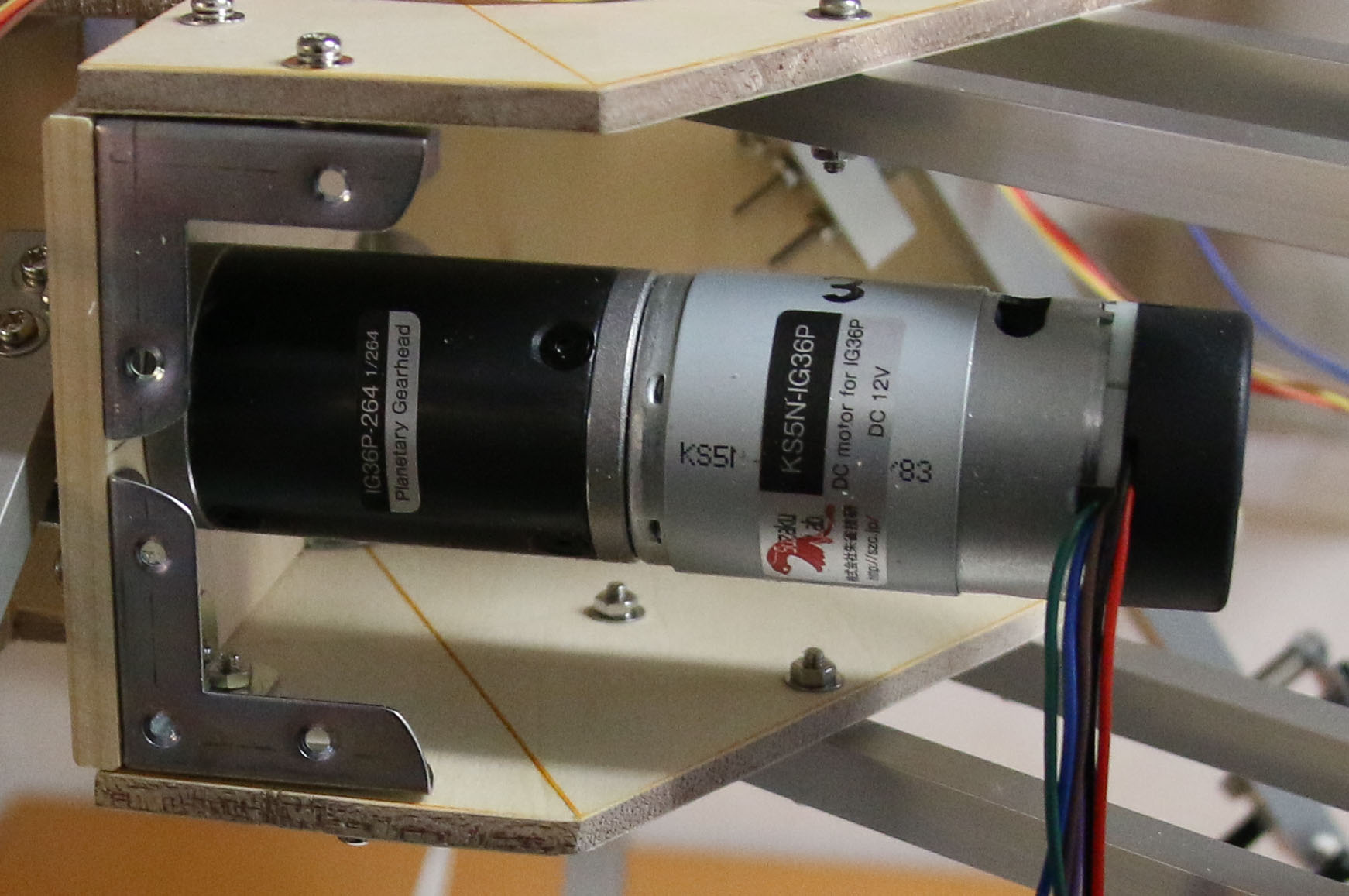
Those are KS5N-IG36Ps, bought from a shop in Japan.
- Speed: 20rpm
- Torque: 25kgf-cm
- Voltage: 12V
- Current: 2A
- Gear: 1/264 downscale
- Rotary encoder: 14 pulses per rotation
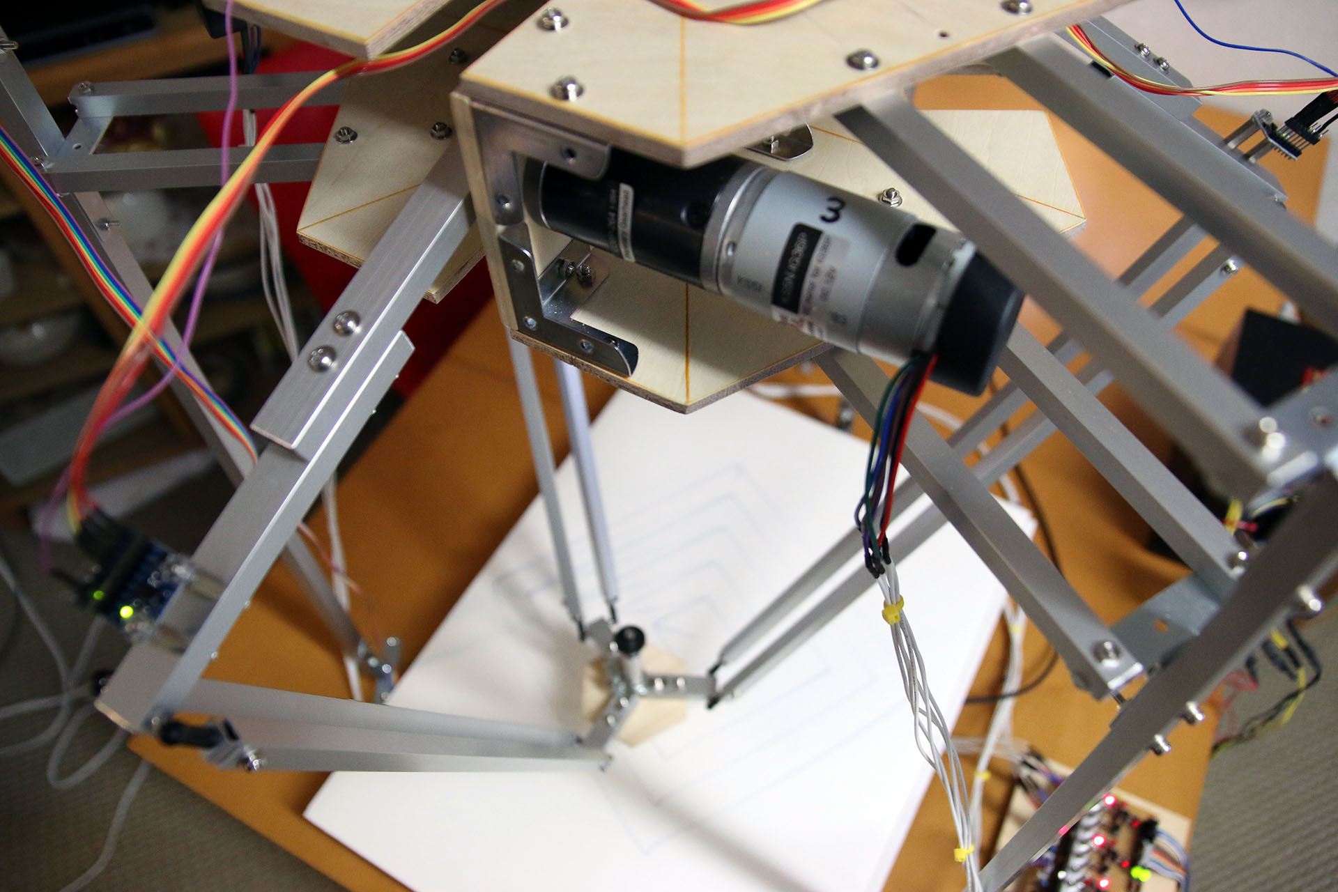
The specs are indeed intriguing, one might even argue that the decision to go with geared DC motors was reasonable. Just look at that torque! 25kg-cm! Here are some more pics of the building process.
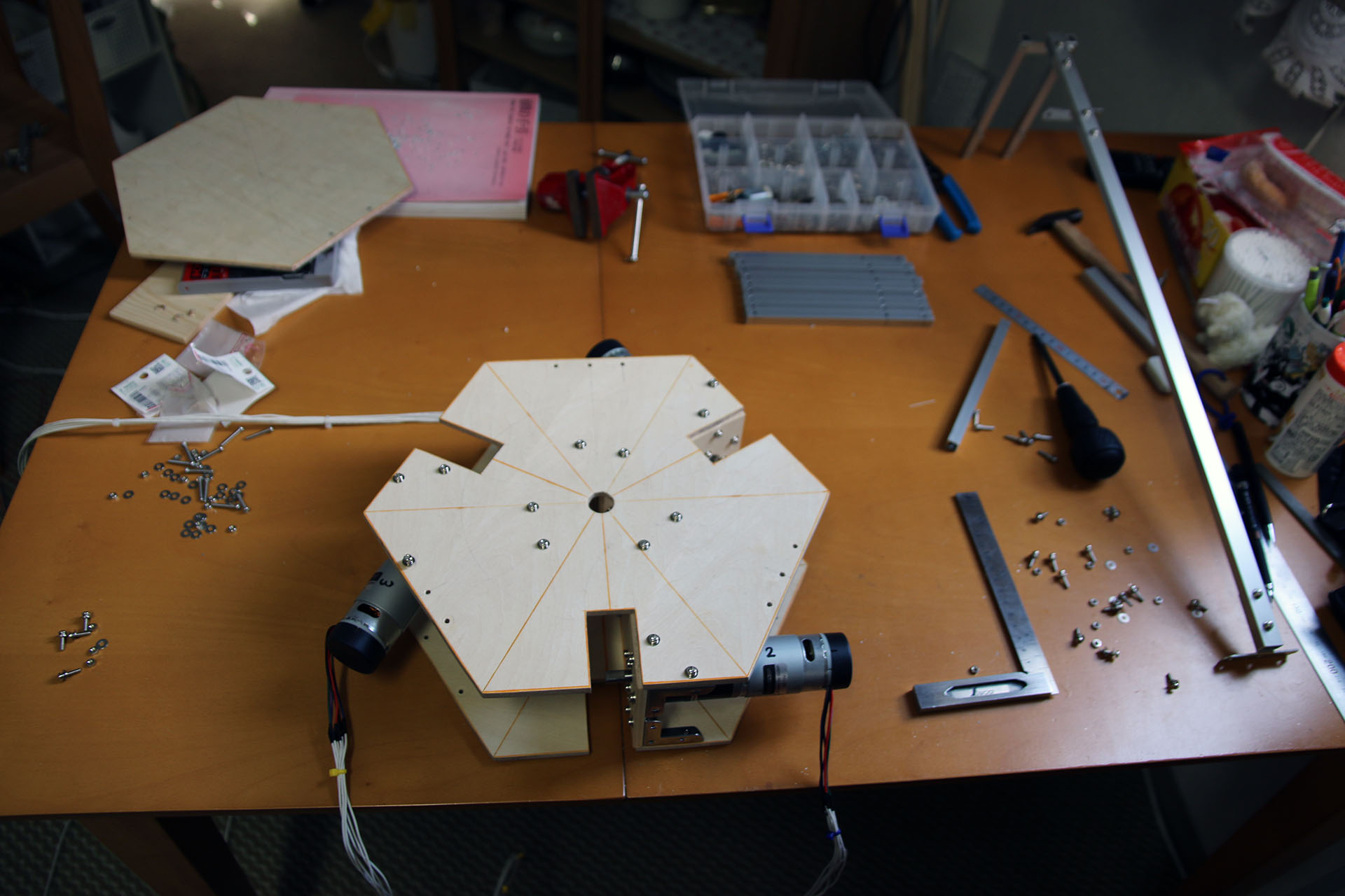
I decided to use wood to build the base of the Arduino Delta Robot.
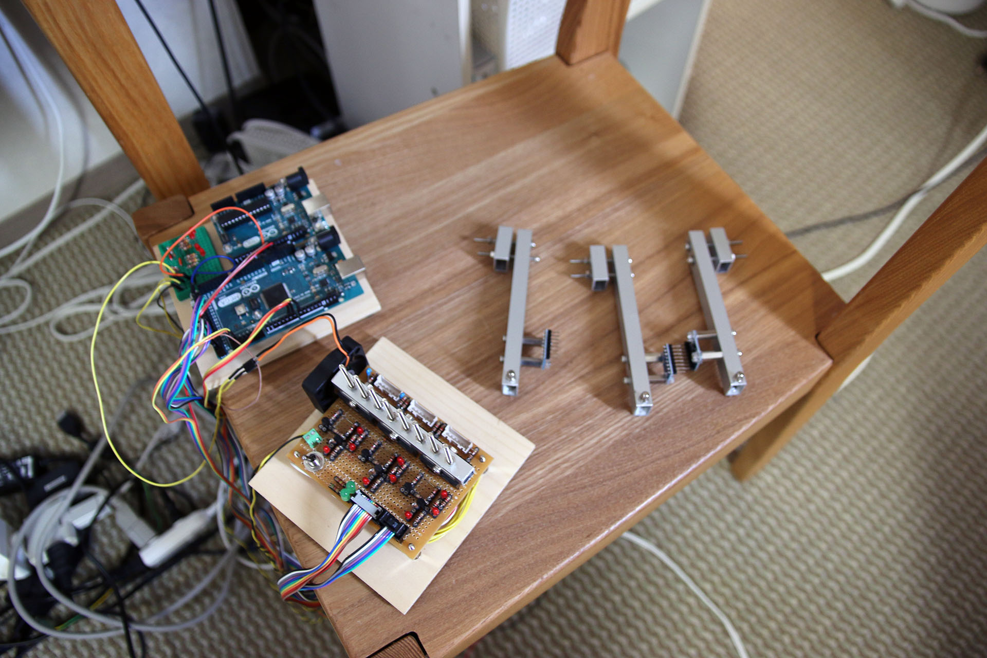
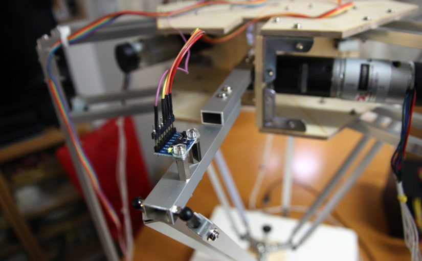
The Arduino Mega with DC motor driver board and 3 accelerometers. Those accelerometers are used to get the Delta Robot to calibrate itself on startup.
Moving Footage
And here’s a video of the Arduino Delta Robot drawing squares:
The Wiggly Lines Problem
And here are the squares.
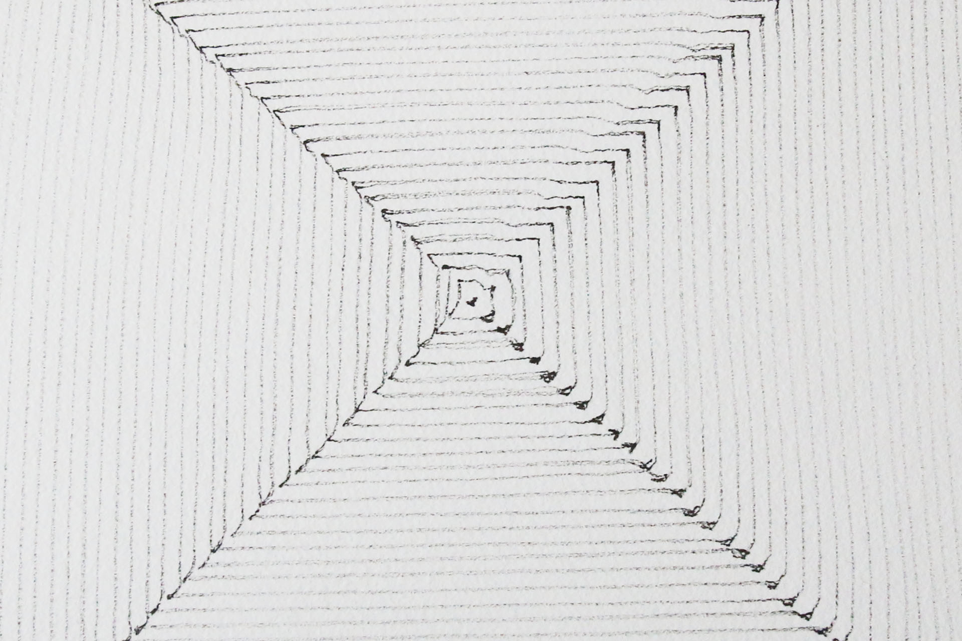
“Interesting.” you might think. “The lines seem to be more or less straight – expect for the start / endpoints. How come?” Well, as it turns out it is quite hard to tune the PID controllers for the DC motors just right. In fact, the PID approach might be impossible altogether. Or it needs to be improved by some other mathematical concept.
Here’s what causes the wigglyness around the start / endpoints of the lines. Whenever we send a new target position for the end effector to the Arduino, the Arduino calculates how much all of the 3 DC motors will need to rotate in order for the end effector to get to the desired coordinates. This is done by applying inverse kinematics. Here’s a very informative internet publication by R.L. Williams II explaining the mathematical concept and providing all the formulas needed for the inverse kinematics. Back to the wiggly lines phenomenon. The Arduino calculates how many pulses each DC motor needs to rotate. The result might look something like this:
- Motor1: 1024 pulses
- Motor2: 56 pulses
- Motor3: 2020 pulses
It’s worth mentioning that the 14 pulses per rotation are measured before the gear scales the rotational movement down. But you might already figured that that’s how the ball rolls. The problem now is that in order to draw a straight line, it is necessary for all motors to start, rotate with a constant speed, and then stop at the same time. This linearity can not be provided by my DC motor PID combination. And this is what causes the wigglyness. The motor with 56 pulses to go might start rotating a lot later then the one with 2020 pulses to go. Another thing I noticed was that 14 pulses per rotation might be on the low end. For the PID to function correctly, the higher the resolution of the rotary encoder the better!
Even though the precision while moving is miserable, the point precision after all motors have stopped was okay. This is why I decided to mount a Raspberry Pi camera module on the end effector and do some pick and place experiments. Read more in the next post!
hi my name is Carlos.
You think you can share the robot’s programming files, I have a project at the university and they would help me a lot.
please. I fron Mexico.
REGARDS
Hi,
Can you share the diagram, I would like to
to do this job?
I can not compile EncMotorDriverMultiDrive.ino with the libraries that I found in net, I use the IDE of Arduino 1.8.7 multiple errors appear. Could you tell me what IDE used and where to find the libraries with the appropriate version. .The repository can not be downloaded.
Regards
Hi Rafael,
I updated the Github repository. It now contains all the necessary libraries in the “used libraries” folder. Just copy them into your MyDocuments/Arduino/libraries folder and you should be able to compile EncMotorDriverMultiDrive.ino.
https://github.com/T-Kuhn/DeltaPicker
Hi T-Kuhn
Thanks for the reply, I have used the updated libraries and .ino file and I still get this error:
In file included from C: \ Users \ User \ Documents \ Arduino \ EncMotorDriverMultiDrive \ EncMotorDriverMultiDrive.ino: 2: 0:
C: \ Users \ User \ Documents \ Arduino \ libraries \ EncMotControl / EncMotControl.h: 21: 9: error: ‘PID’ does not name a type
PID pid;
Please, what version of Arduino IDE do you use?
Tanks in advance
Solved. I have put PID.cpp and PID.h inside the same directory of the EncMotControl library with EncMotControl.cpp and EncMotControl.h
I want code , pleaseeeee
Here you go:
https://github.com/T-Kuhn/DeltaPicker