In the previous post, I wrote about how I decided to build an Arduino Delta Robot. In this post, I will show you how I added some simple Computer Vision to the project.
Because the line drawing capability of my Delta Robot was a bit limited (wiggly lines), I figured that pick and place might be its true calling. I added a cheap 3.3V air pump and a Raspberry Pi camera module to the build and patched together some simple Computer Vision algorithms. The algorithms used here are almost the same as the ones I used in this Robot Arm project. Take a look at the Delta Robot Github repository for the source code.
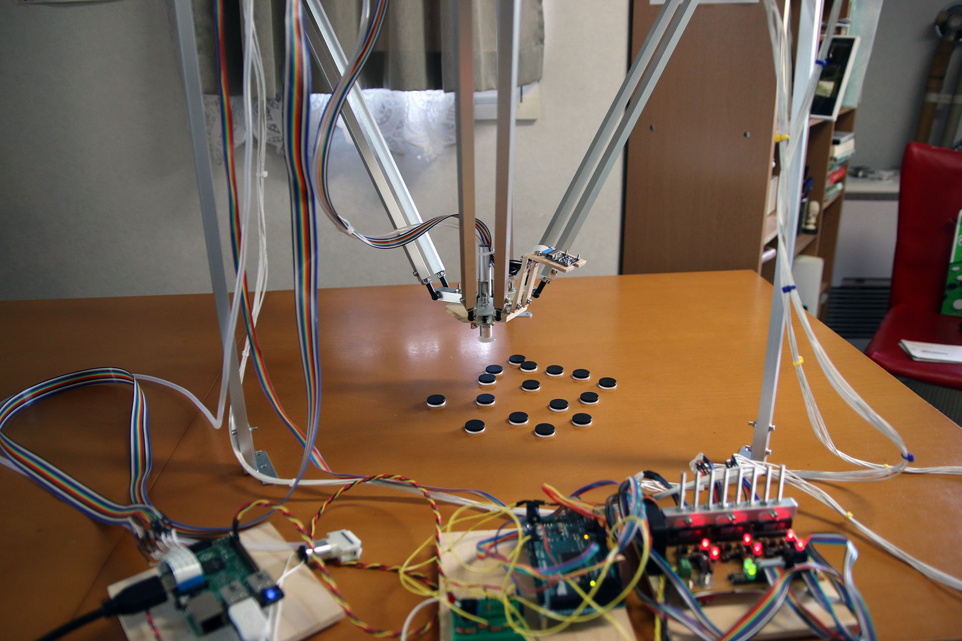
In the image above you can see the whole setup. The image processing works like this: Look for pixel areas with high contrast, compute the area and centre of the object, and then, move in such a way that the thing can be picked up. I made a video of the Delta Robot picking and placing small objects with the Computer Vision processing edited into it.
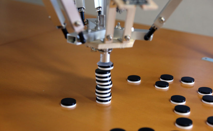
As you can see, The Delta Robot is trying to build a tower. Some time ago, I reused the wooden hexagon which I made to hold the DC motors in the ping pong juggling machine project.
First, I wonder how you control your delta robot. You send some commands (are they G code? or other command you invent?) to control it, don’t you?
Second, how can you guarantee the kinematic accuracy of your delta robot? (it has offset in z axis if you only command to go straight along x axis?) do you have a calibration?
Hi Irx666,
The commands aren’t G-code. I made up some sort of scheme. It was probably something as simple as “x123y0z32\n”, where the linebreak “\n” tells the listening Arduino that the command is now over and the numbers after the letters indicate how much the Raspberry Pi wants the Arduino to move each motor.
I am not sure how to answer your second question, because I do not fully understand it. There is a calibration. The home position is such that all the arms are horizontal to the ground. I am using accelerometers (attached to each arm) to figure out when each arm reaches its horizontal position.
Maybe you are referring to the fact that the endpoint is moving up and down a little even in times when it probably isn’t meant to move vertically at all (e.g. when it’s supposed to move parallel to the table it is mounted on.) That’s because of the PID algorithm I am using to position the motors. Since I am using DC motors, it is hard to get them to rotate at an exact speed. I got the rotary encoder signals as an input, but it’s still quite difficult. The vertical movements are because of this difficulty.
Hi T-Kuhn,
Thanks for your reply, really appreciate!
Actually I am using stepping motors to control my delta robot which I made two weeks ago (It was a open-loop control……).
I have tried opensource codes such as GRBL and Marlin, so I used G code to control. Using GRBL, When I control it to move horizontally I found it had a vertical move indeed as you said. I thought it was because the inapplicability of the linear interpolation algorithm. I couldn’t figure out.
As you wrote in blog, I bought a GY-521 to calibrate the angle before it worked on.
It is a project of my graduation design and it will last around less than 3 months. So I don’t have enough time to make it perfectly but I’ll try my best.
All in all, in view of that you are a pioneer, hope for a contact next time.
Were you able to fix the unintentional vertical movements when trying to move in a straight line parallel to the table?
I just remembered that I had a similar bug when I was creating my delta robot. In my case, it was because the conversion rate used to convert the IK-result value (in radians, if I remember correctly) to steps to move of the motor wasn’t set up correctly.
Hi lrz666
We will also use grbl controller in our graduation project. Has grbl controller accept computer vision?
I mean how did you use them together?
Hello there T-Kuhn,
I was wondering how did you get the object coordinates relative to the world frame, I get that the camera position is fixed and you only need to get the (X, Y)coordinates as you have fixed z coordinate. If you could let me know how did you find the center of the object using its pixels and converting them to x,y coordinates relative the image frame assuming our real-world center (0,0) is at the middle of the camera view, I sincerely ask your help in this as I am trying to find the objects coordinates when an object is placed in the camera’s field of view. Thank you
Hi Adnan,
This is how I did it:
– First, calibrate the camera by putting one target object directly under the suction cup (you can actually see how I calibrate it in the video.)
– The calibration works like this: Because we put the target object directly under the suction cup, we know that it’s exactly in the right spot in order to be picked up. Next we move the suction cup up to the height where we want to take a single image with the camera.
– Next we take a single picture.
– We Search for accumulations of black pixels (the target objects)
– Since we are calibrating there should be only one (the one which we placed directly under the suction cup.)
– We calculate the centre of it by figuring out how many pixels wide and high the target object is.
– After we got the centre we look where the center is in the image, we just use “pixels” as our unit of distance. We could also calculate where the center is relative to the center of the image, but it really doesn’t matter.
– We might get something like this: x: 12 pixels, y: 128 pixels.
– Now we know, that whenever we take a picture and there is a target object exactly at the position x:12 pixels, y: 128 pixels, we can just go straight down and pick it up.
That’s the calibration. Here’s what we do after the calibration when picking up all the target objects:
– Go to the “take image” height (this, of course, has to be the same height as we used when taking the calibration-image.)
– Take a picture.
– Calculate all the centres of the target objects in the picture.
– Example: there might be a target object at x:65, y:50
– Now, all we have to do is move in such a way that the object at x:65, y:50 shows up at x:12, y: 128 the next time we take a picture. To calculate the direction to move, we just take the difference: x: 12-50, y:128-50 -> x:-38, y: 78.
– Now we know that we need to move -38 pixels in the x-direction and 78 pixels in the y-direction.
– You might want to figure out how many mm that is. But you could also skip the millimetres if you know how many pixels your delta robot moves in the x-direction after sending it the command to move, for example, exactly 1mm in the x-direction.
– Once you know how much pixels you machine is moving when sending it a certain command, you can move it in such a way that, when taking another image, it should be fairly close to x:12, y: 128.
– Correct one more time (that’s what my delta robot arm is doing at least)
– go straight down and pick the target object up.
Hi, T-Kuhn!
Let me define these below. If we name the two figures when you do previews calibration——the lower z-coordinate(i.e.,vertical direction) will be called fig1, the higher z-coordinate called fig2.
When you do “Correct one more time”, you have moved to a ”rough”(Why ) position based on the fig2 using so-called relative coordinate. Then you do a correction based on fig1 and a serial of photos you catch on the same z-coordinate with fig1,right? Essentially, this process is to find the correct x and y coordinate by some photos and doing conversion of image coordinate system. Why it is so accurater than getting relative coordinate according to fig2 that you can use to minimize the kinematic error, is it because when z-coordinate get lower the object on image get bigger so that the accuracy of image processing will get higher? I mean, how these process work?
I ended up taking a second image and zeroing in a second time just because the results were better that way, that’s all there’s to it. I encourage you to find a solution that works for YOU with YOUR setup. Start by making sure everything works as you think it works (mainly the IK part). Spend some time on the maths. Once you are able to send target coordinates and have the thing move accordingly getting it to move above some object isn’t that hard. You just need to advance step by step using your own methods and making sure there are no bugs in the code and everything is working as you think it is. There is no “One right way” to do this. I did my best to explain how I ended up doing it in the comment above but at the same time I encourage you to find your own method of how to get it to work.
I want G-code pleasess
What the spherical joints are you using? I can’t find thats at AliEpress.